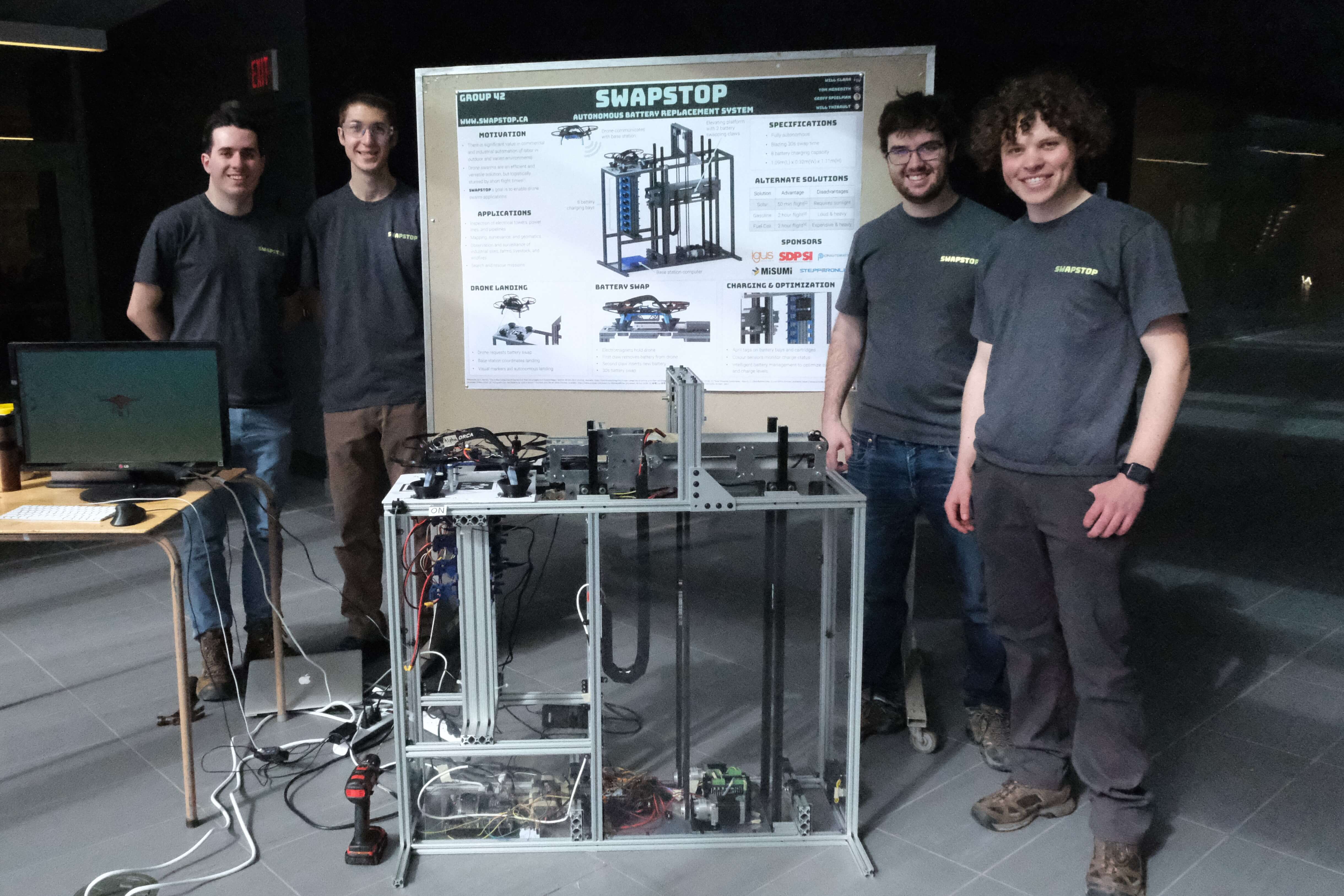
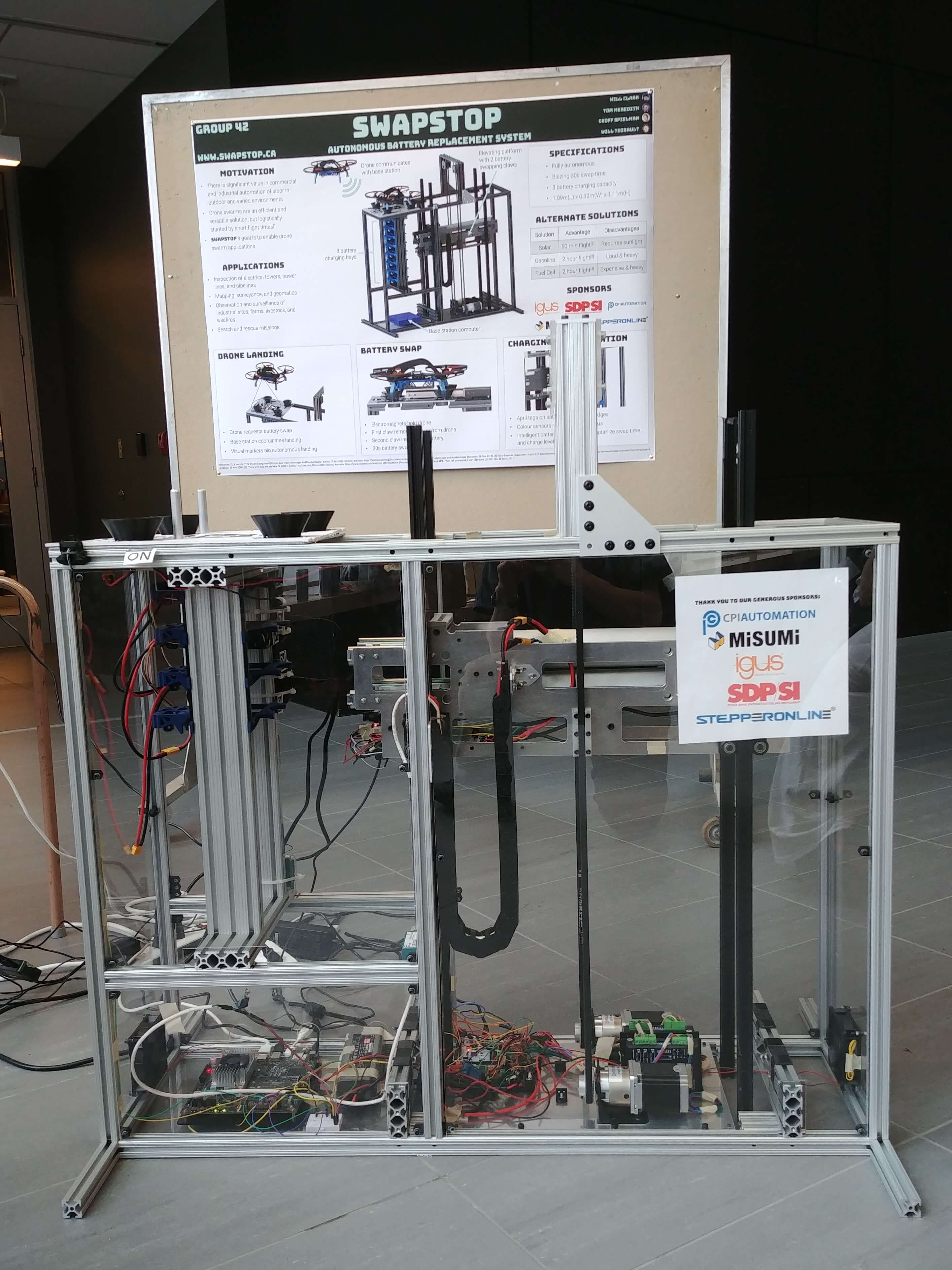
Autonomous Drone Battery Swapper
For my fourth-year design project (capstone project) I worked with three fellow mechatronics engineers to design an autonomous drone battery swapper. I left the electrical and software aspects of the project in their more-than-capable hands and took care of the mechanical side of the project, which this page focuses on. Our final prototype contained 1373 parts and tied for the Baylis Award for Prototype Quality which is awarded based on "the best quality prototype that demonstrates and tests the designed engineering solution, including fabrication, material selection and suitability to meet project objectives".
I recommend watching the project overview video and playing with the 3D model before diving into the project details below.
Project Motivation
Thanks to recent innovations in control theory and wireless communications, multi-rotor drones are now capable of coordinating together in swarms to complete complex tasks such as search and rescue missions, electrical infrastructure/pipeline inspection, and agricultural surveying. However, these applications are currently limited by short flight times of approximately 20 minutes for most modern drones. A portable, fully autonomous base station could keep a swarm airborne indefinitely by replenishing each depleted battery in under 30 seconds, enabling these exciting applications in the future.
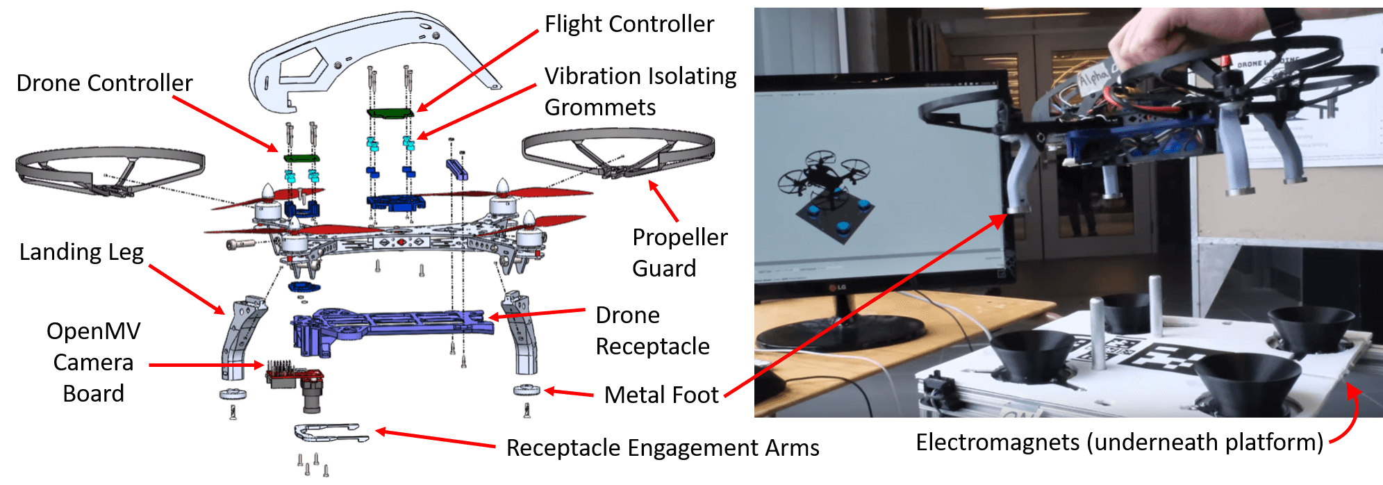
Landing Process & Drone Modifications
When a drone's battery level is low, it sends a swap request to the base station via a radio link. Once granted, the drone approaches the landing pad via its own autonomy (beyond the project scope) and uses an on-board camera and visual indicators on the landing pad to localize itself and descend into the guiding cones. The drones have 3D printed legs and metal feet which are locked in place during a swap by electromagnets underneath the landing platform.
We purchased drone kits and modified them rather than designing our own drones to save time and prove the system could be adapted to most commercial drones. Each kit included a flight controller which accepts thrust and attitude commands and flies the drone accordingly. This abstracted away the low-level control loop of monitoring the accelerometer/IMU sensors and sending appropriate speed commands to each motor's ESC (electronic speed control) which simplified the project.
We added a camera board and a second microcontroller (the ‘drone controller’) which runs our custom firmware. The drone controller communicates with the base station via a radio transmitter, takes position estimates from the camera board, and runs a high-level control algorithm to instruct the flight controller where to fly the drone. Unfortunately we didn’t have time to complete this software so you won’t see the drone flying in the video, but we did achieve localization which means the drone knows exactly where it is and when to shut off its propellers.
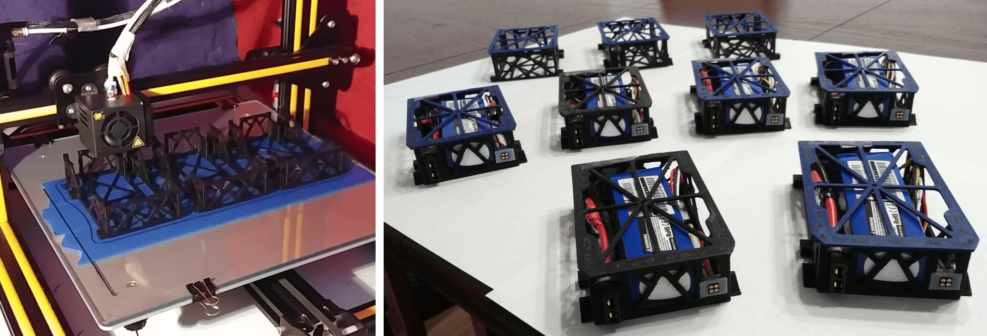
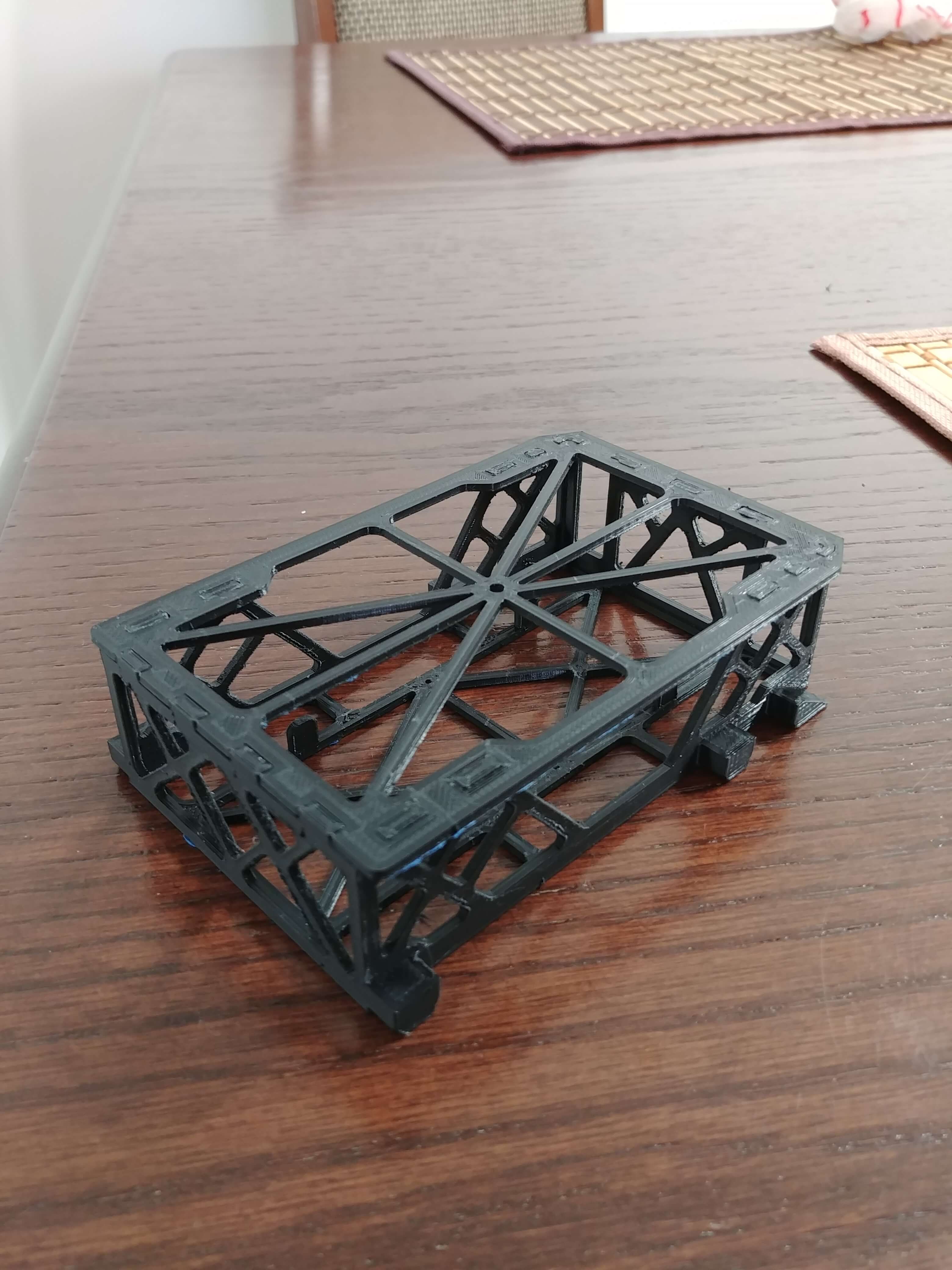
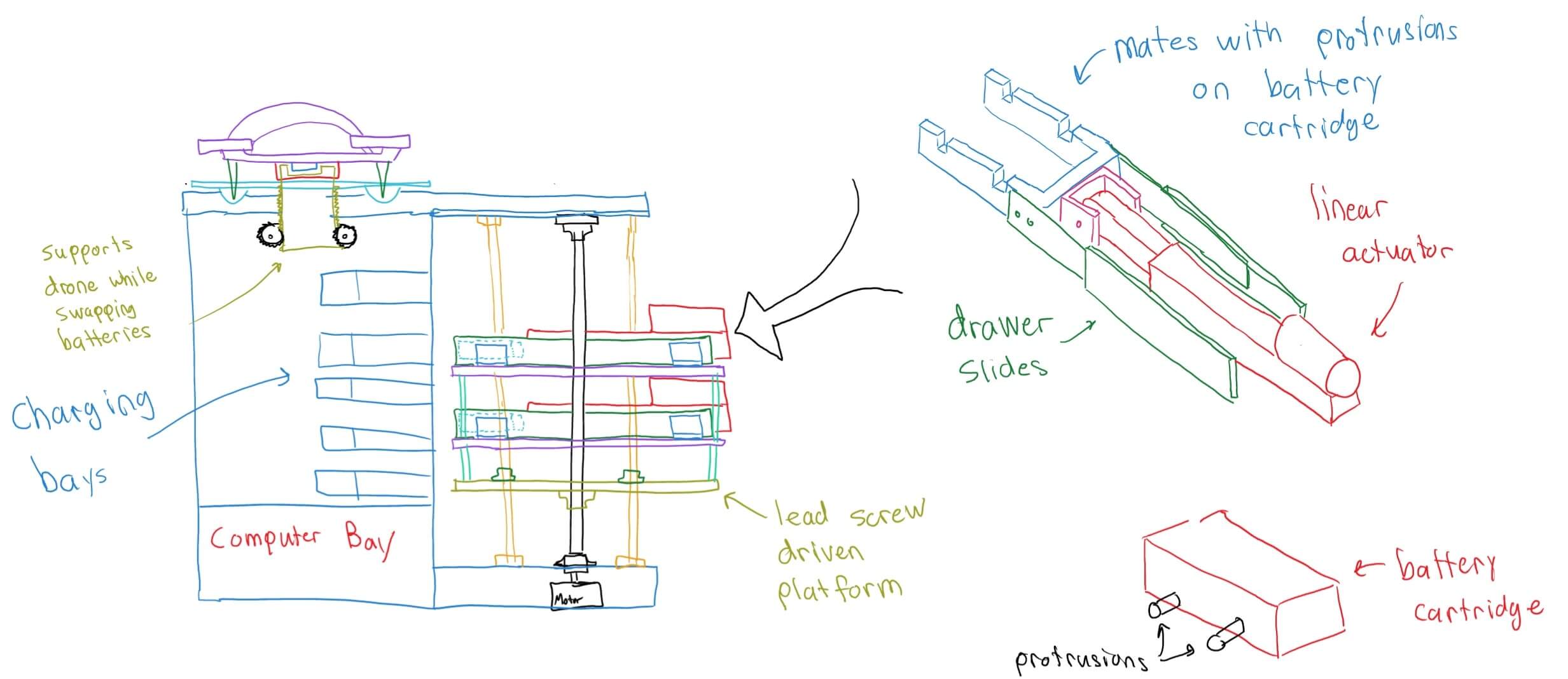
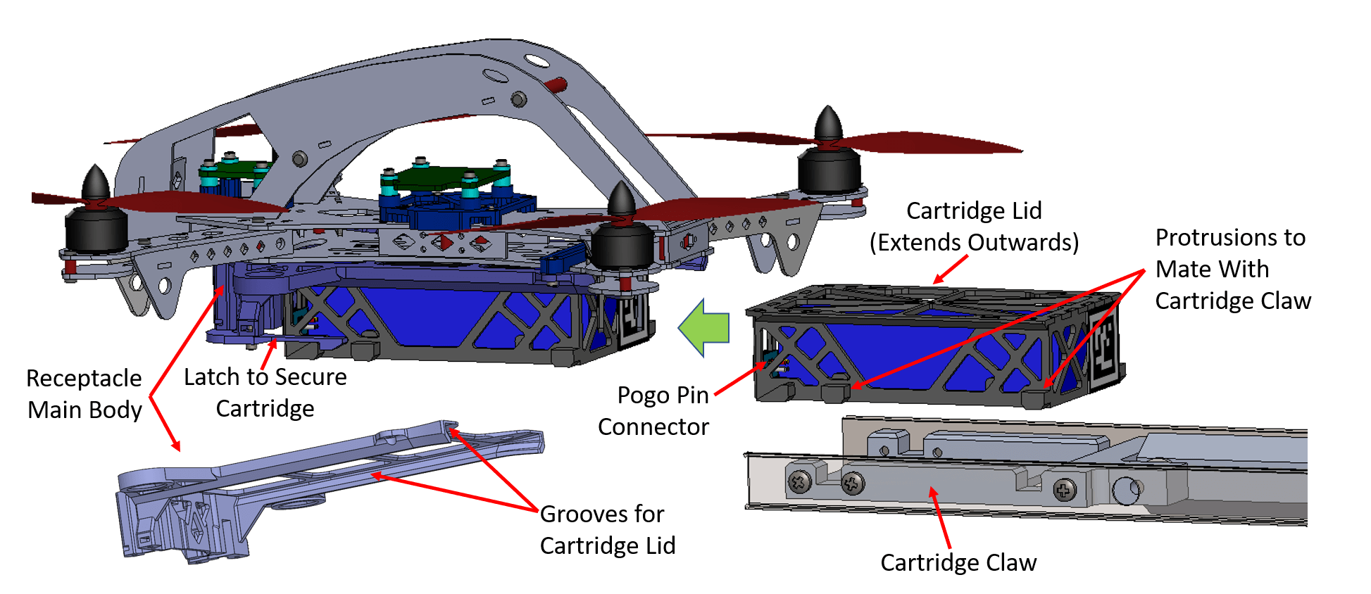
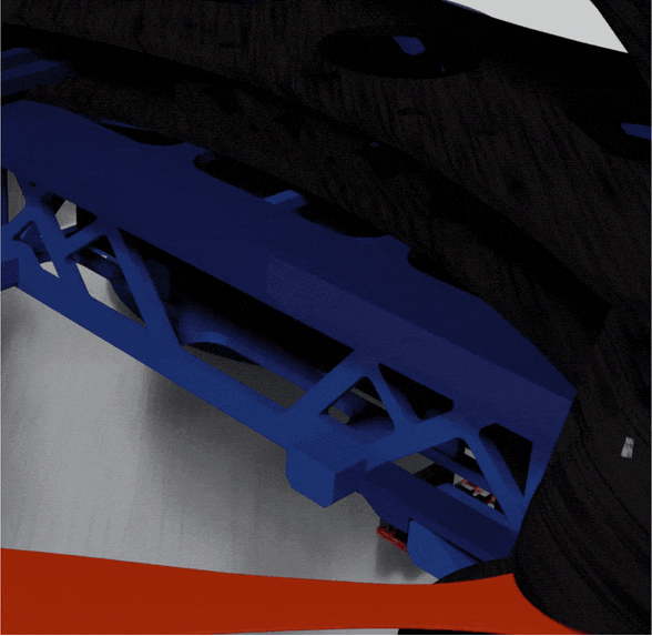
Battery Cartridges and Receptacles
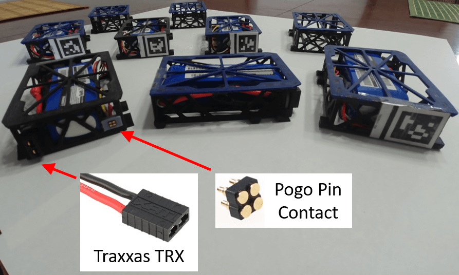
To facilitate rapid swapping, we designed a custom receptacle attached to the drone and a battery cartridge with two electrical connectors. The large connector is a Traxxas TRX which is designed for RC cars and can handle 60 amps of current. It had the lowest force to connect/disconnect out of all the connectors we tested. The smaller connector is a 4 contact pogo pin target; the pogo pins are in the charging bays of the tower. The four contacts allow the three internal cells of each Lipo battery to be balanced while charging. There are latching arms on each receptable to secure the cartridge in place during flight, however these are disengaged by the 'cartridge claw' of our battery handler prior to extracting the cartridge (see gif below).
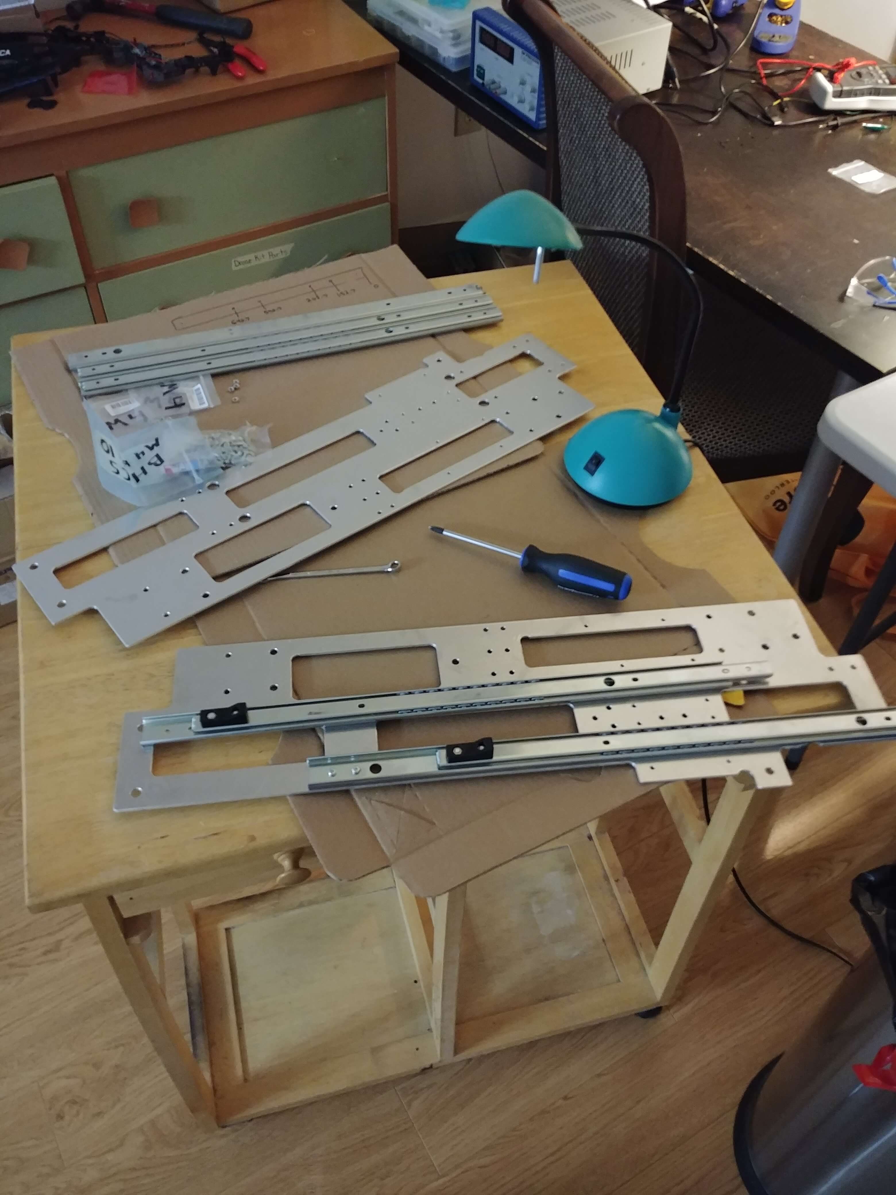
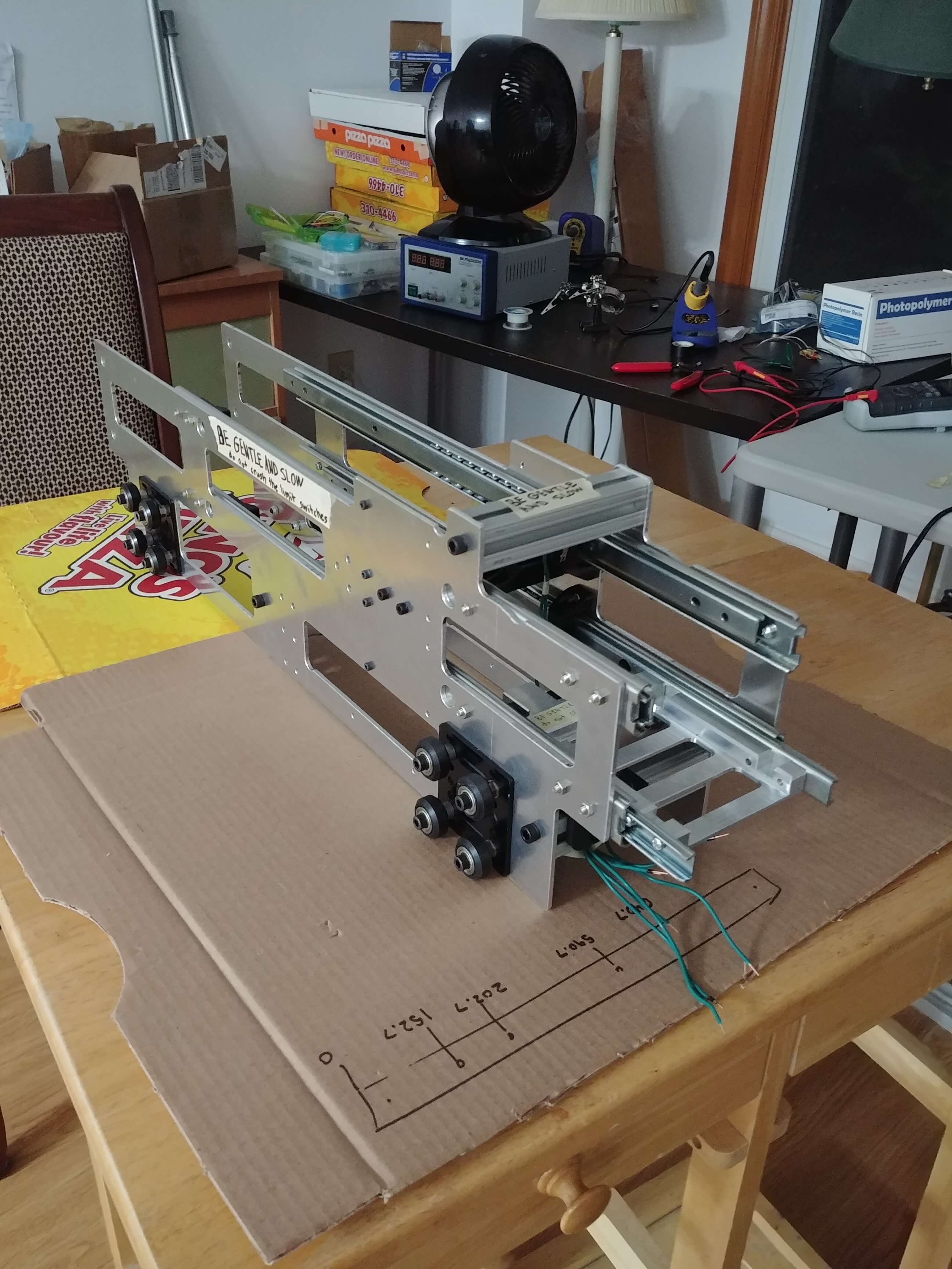
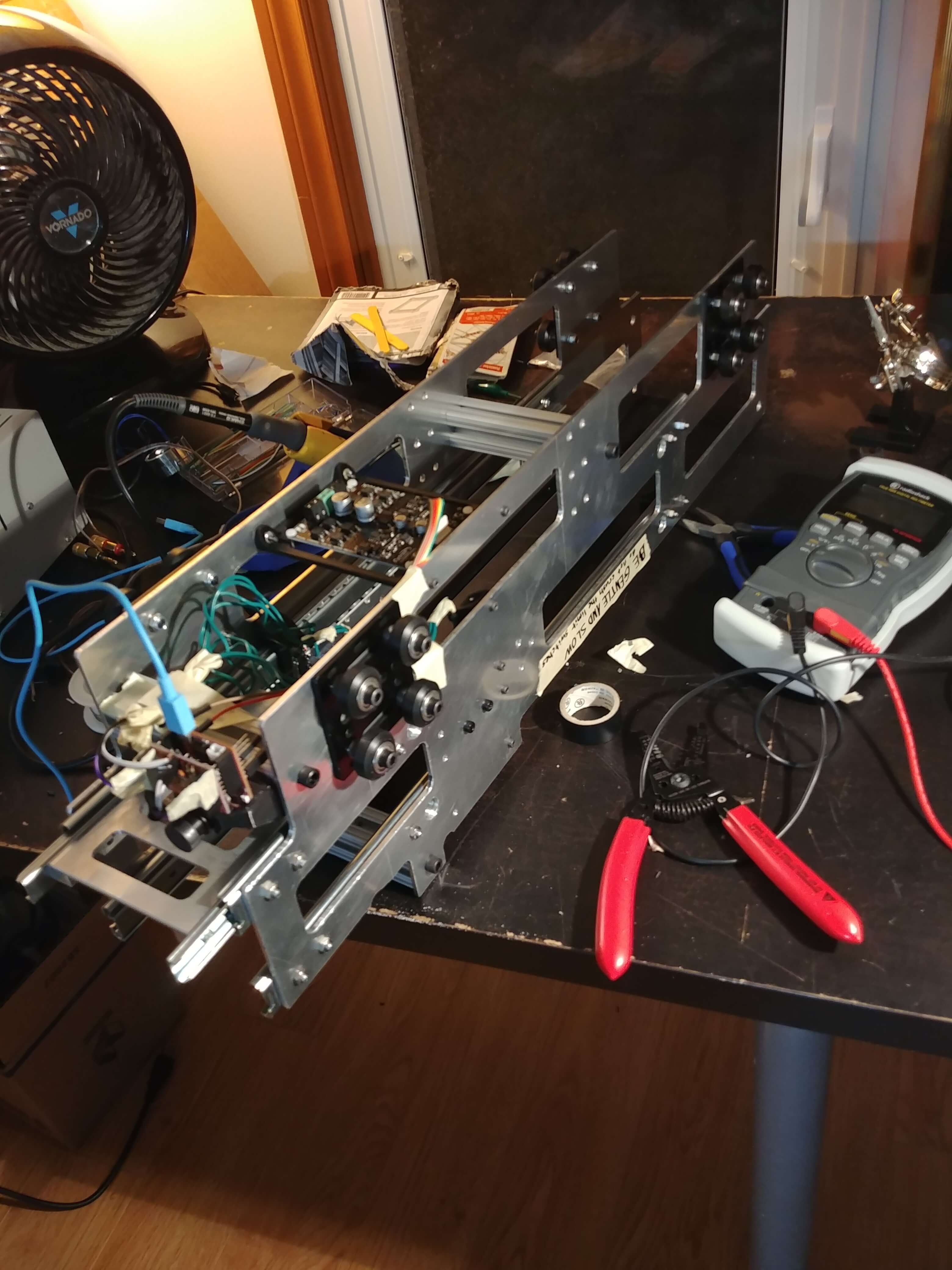
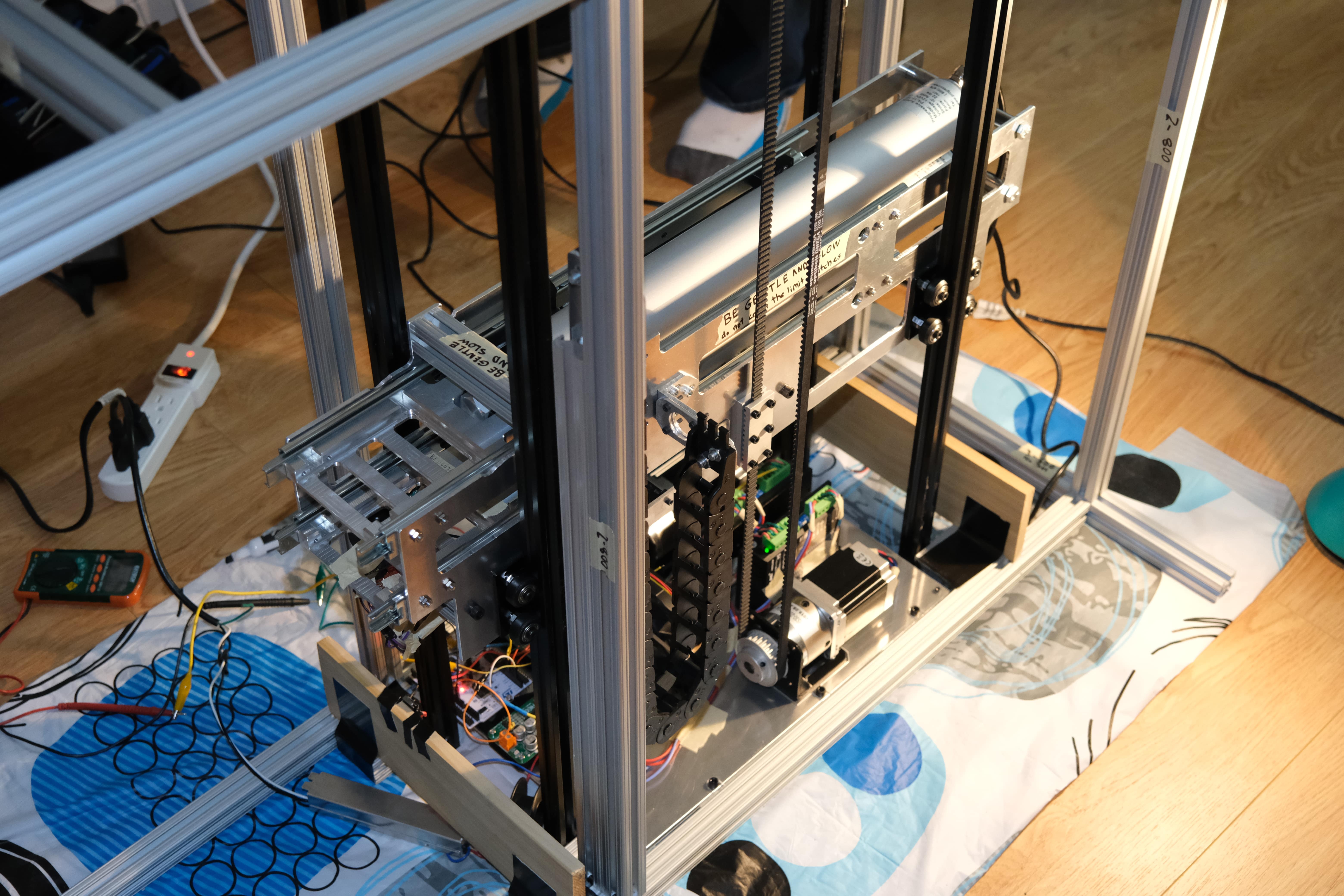
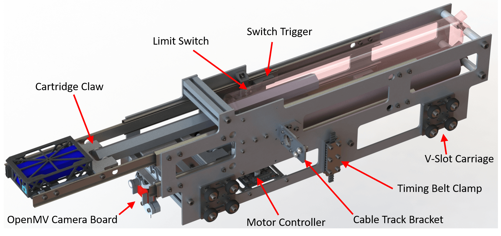
Battery Handler
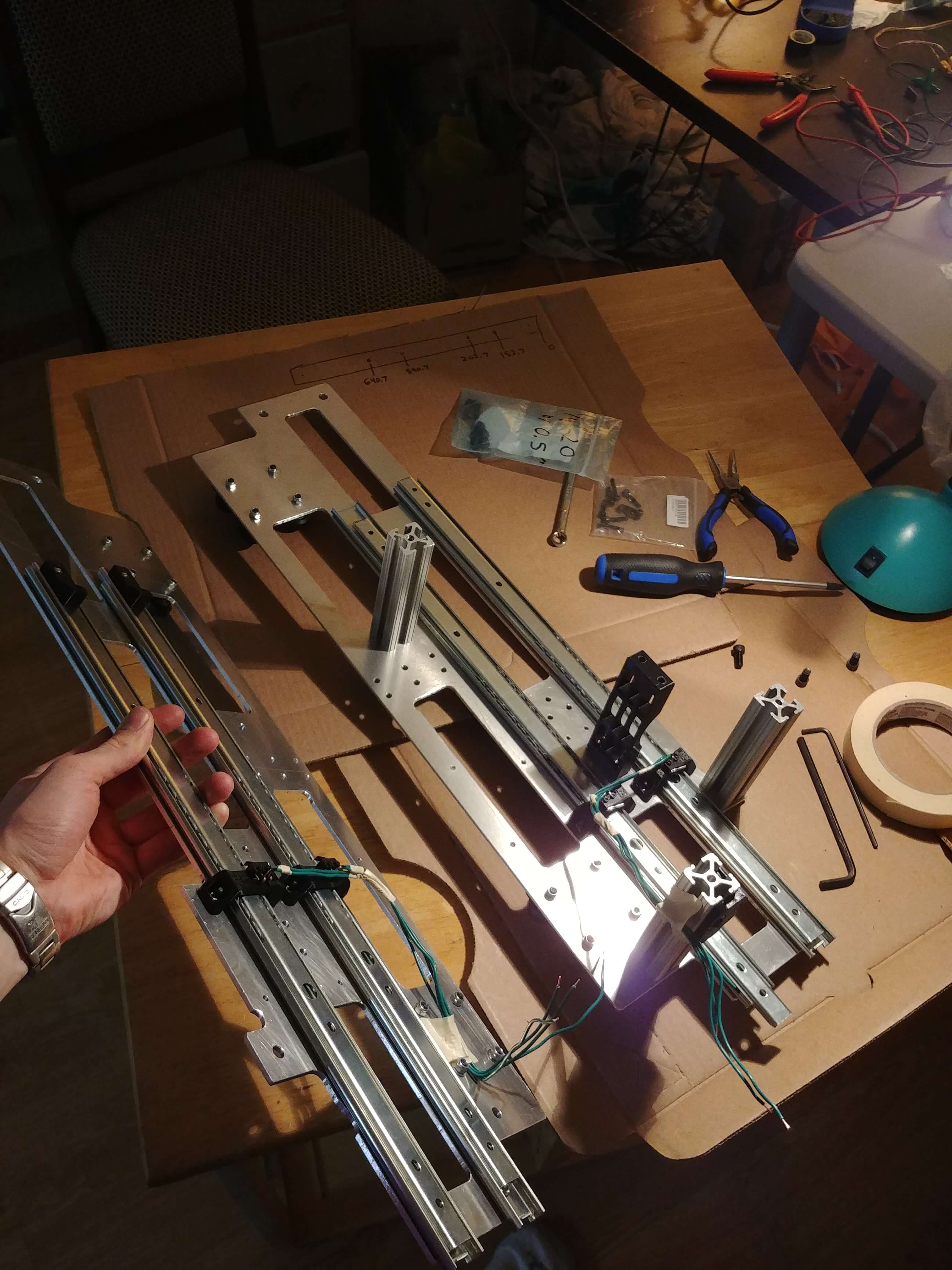
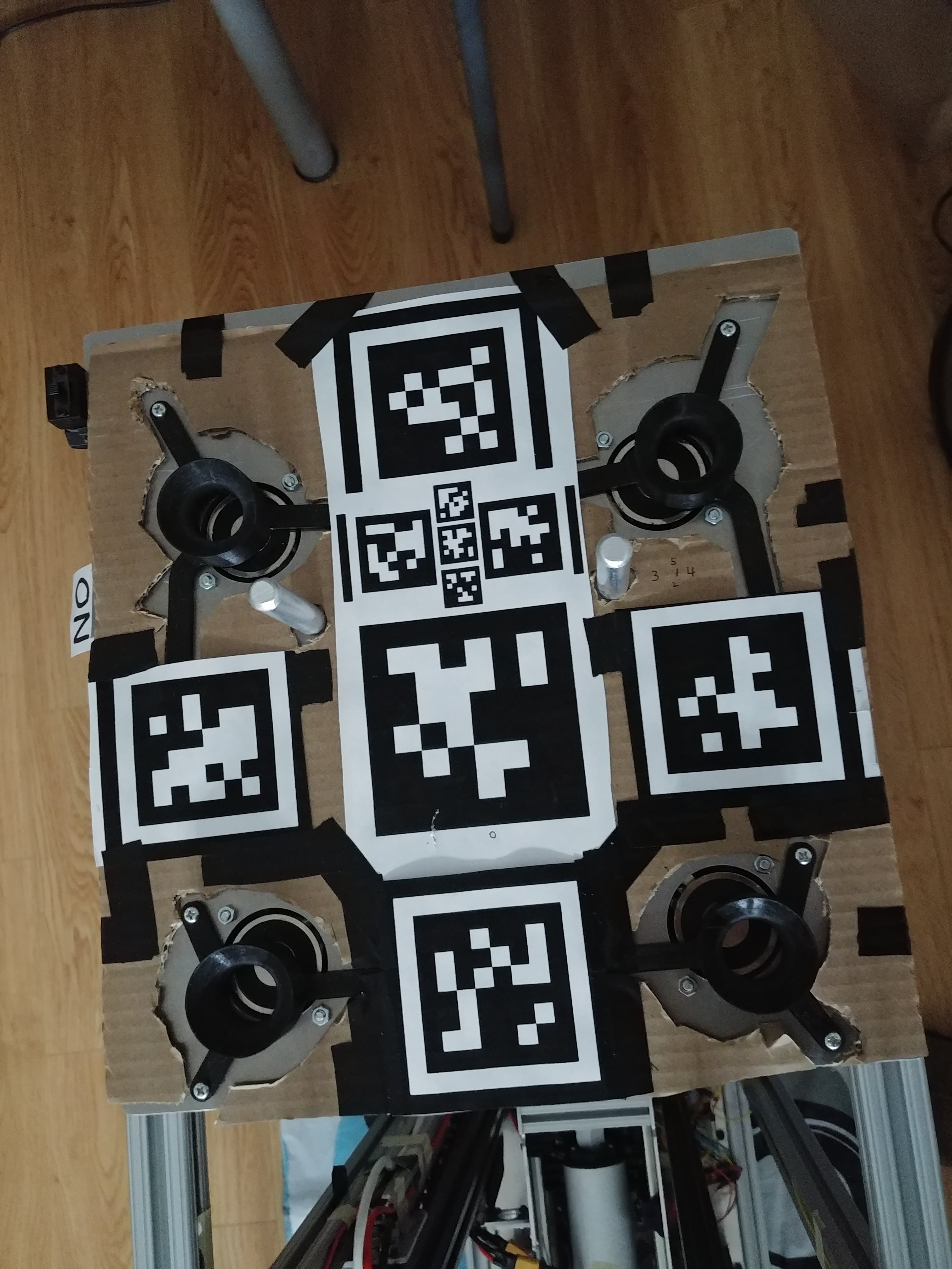
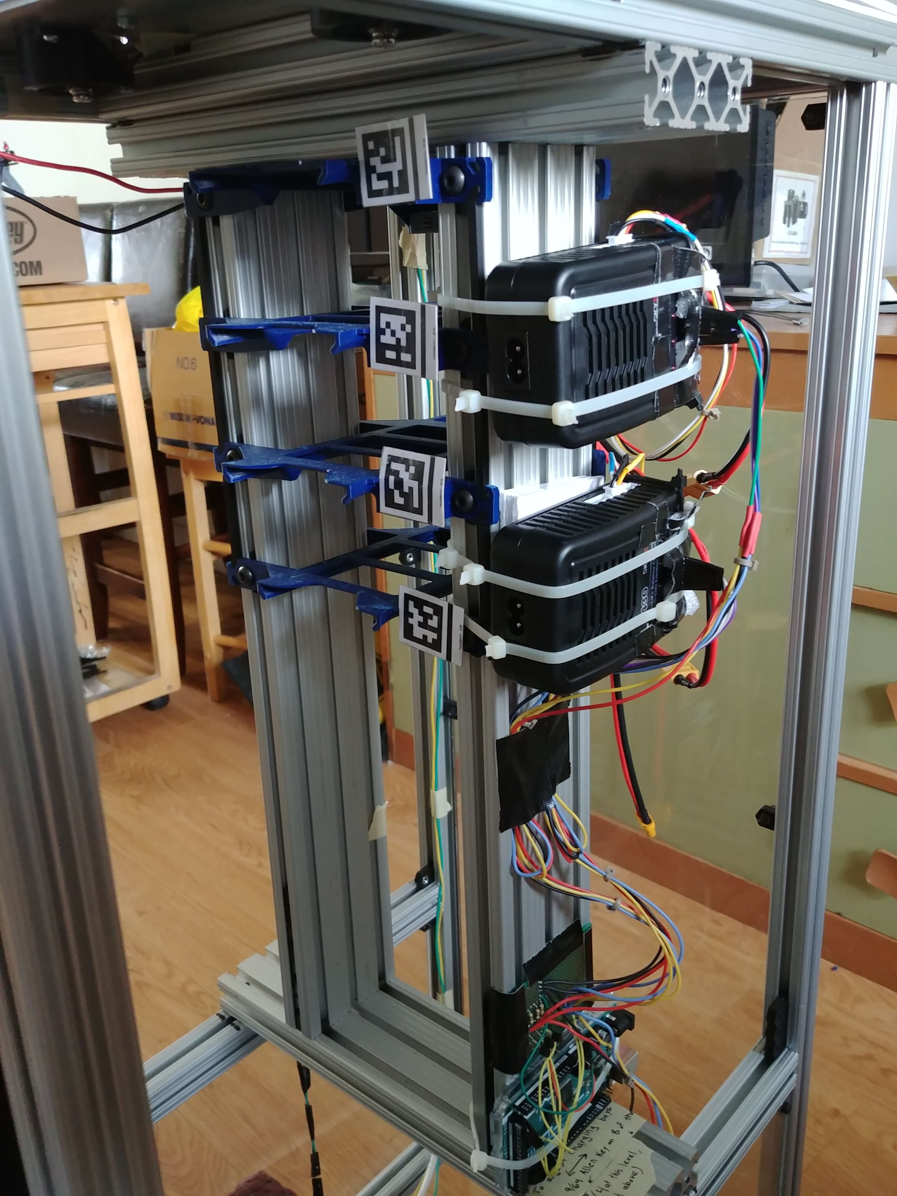
Cartridges are transported around the tower by our battery handler which features two linear actuators: one to remove the depleted battery from the drone and a second to insert a fresh battery. The actuators move at 5.5 inches per second and are guided by drawer slides. An on-board motor controller drives the actuators and receives commands from the subsystem’s main processor: an OpenMV camera board. Limit switches inform the main processor when the actuators have fully extended/retracted and the camera reads AprilTags (similar to QR codes) off the battery cartridges and charging bays.
Verifying the location of each cartridge is crucial during start-up because someone could manually move a cartridge while the system is powered down. If the system did not detect this change, it might attempt to stow a depleted cartridge into an occupied charging bay, which would be problematic.
There is a cable track connecting the battery handler to the tower frame to prevent cables from getting caught in the moving components or tangled with each other. The battery handler glides along vertical V-slot rails to maintain its alignment and is driven by timing belts attached to its sides.
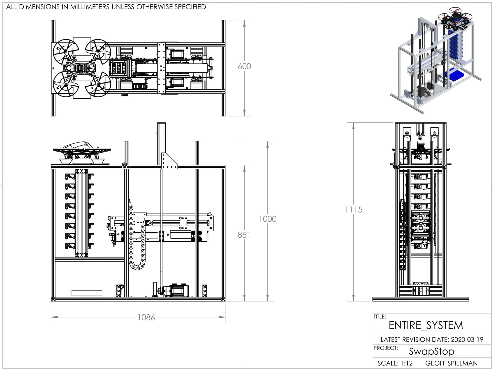
Elevator System
The battery handler is maneuvered vertically by timing belts driven by two synchronous stepper motors at the bottom of the tower. By utilizing microstepping, planetary gearboxes, and relatively small timing pulleys we achieved a vertical accuracy of 0.080 mm with an inertia ratio of 2.65. This means we can position the battery handler at our desired heights extremely reliably, and the 8 kg battery handler can be accelerated and stopped with ease. The top timing belt pulley housings are attached to the tower frame via tensioning screws which can be adjusted as needed.
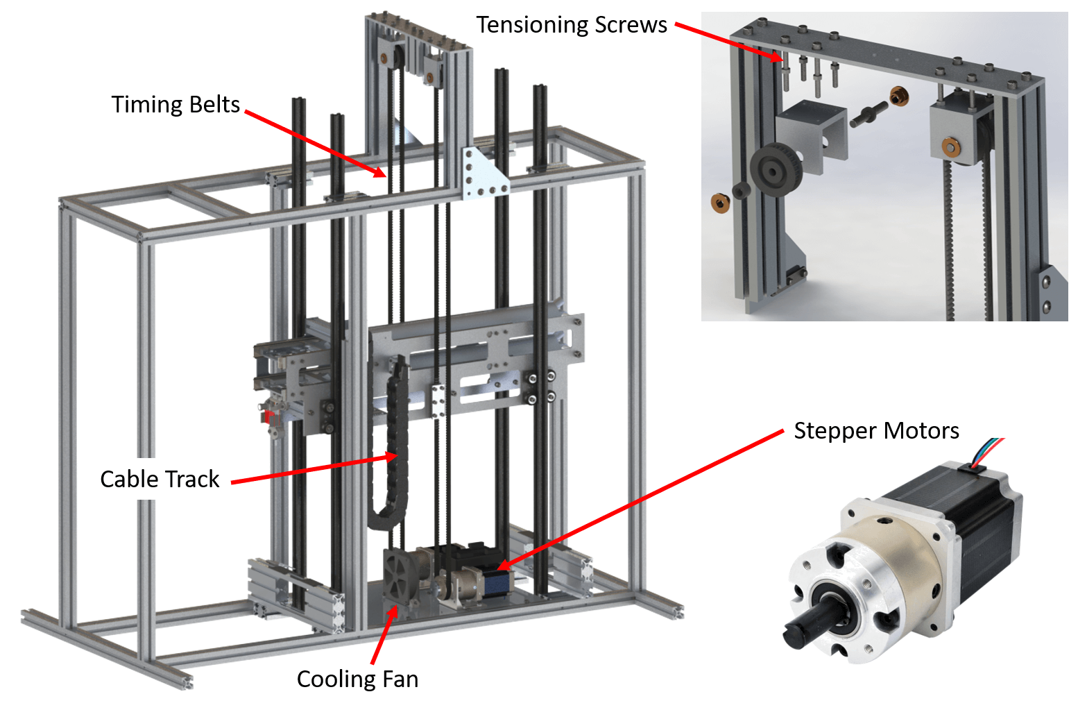
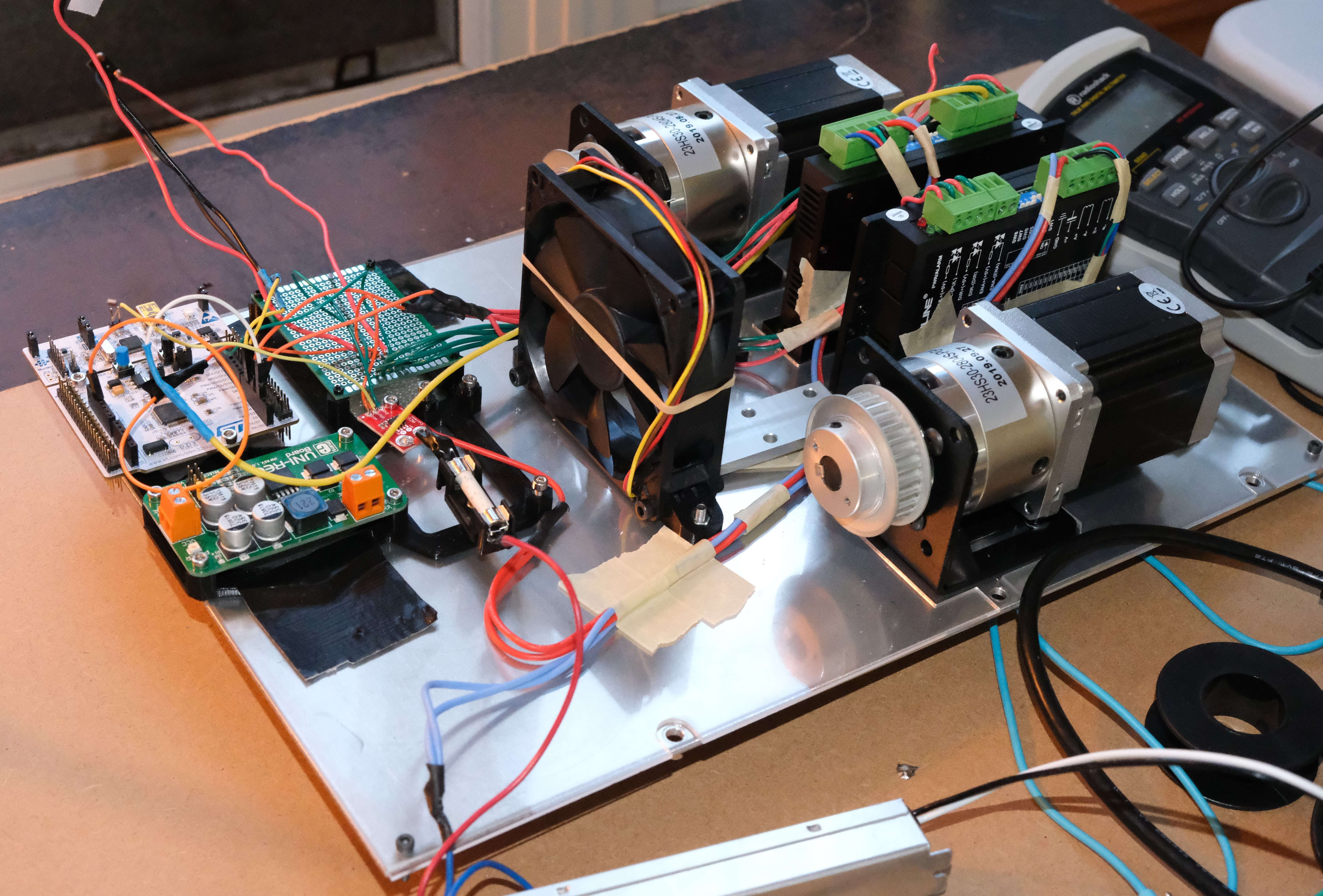
The elevator subsystem is controlled by a Nucleo F446RE microcontroller which interacts with the motors through dedicated stepper drivers. The microcontroller also monitors limit switches at the top and bottom of tower to prevent crashes between the battery handler and the frame.
We also added some fuses, current sensors, and a buck converter on the insulated plate at the bottom of the tower to deal with power distribution and monitoring throughout the entire system. Power electronics produce a fair amount of heat so there are three cooling fans along the bottom of the tower; one is directly in front of the motor drivers.
Charging Bays
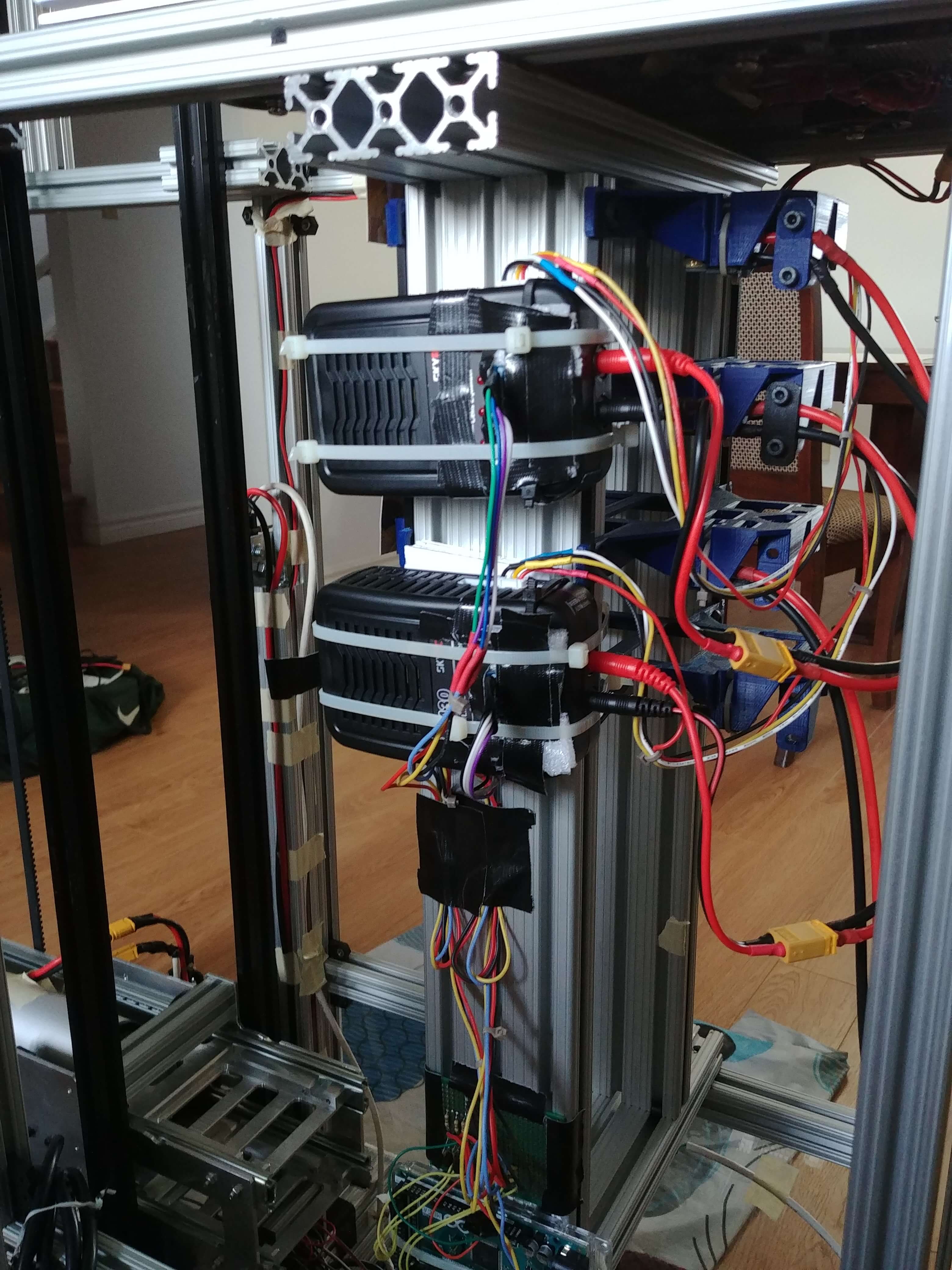
Once removed from a drone, the depleted battery cartridge is inserted into a charging bay below the landing pad. For the prototype we only used two LiPo chargers and the remaining bays are for storage only. We attached colour sensors over the status indicator light on each charger so that the system can detect when a cartridge is fully charged and move it to a storage bay. The master computer for the entire system was a NVIDIA Jetson TX-2 which is located underneath the charging bays. It communicates with each subsystem via a CAN bus and runs a high-level control loop to manage everything from handling a drone’s landing request to ensuring a fresh cartridge is always near the top of the tower ready to go.
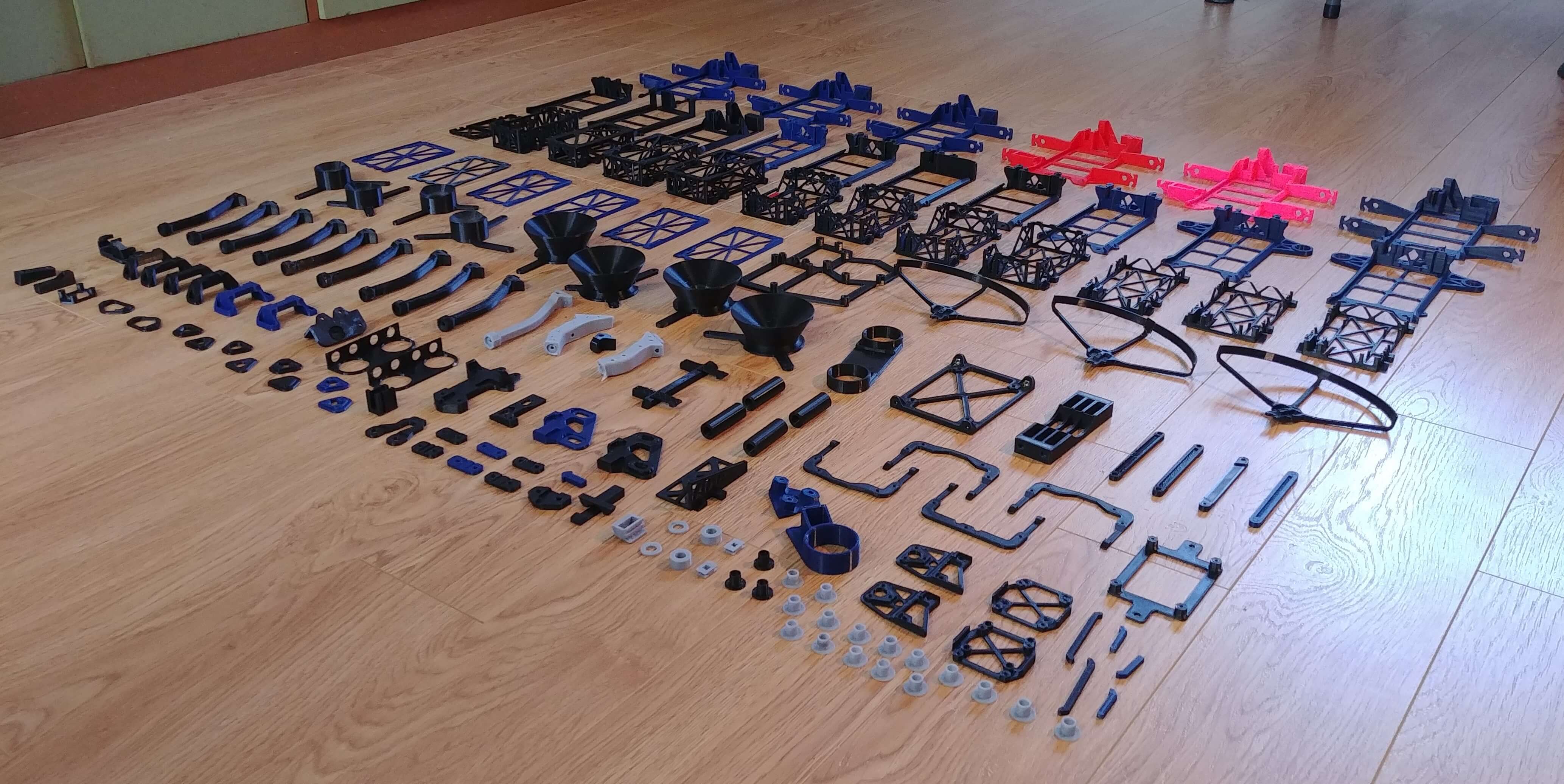
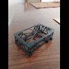
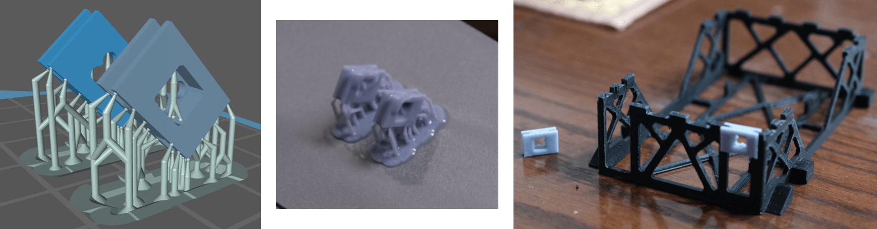
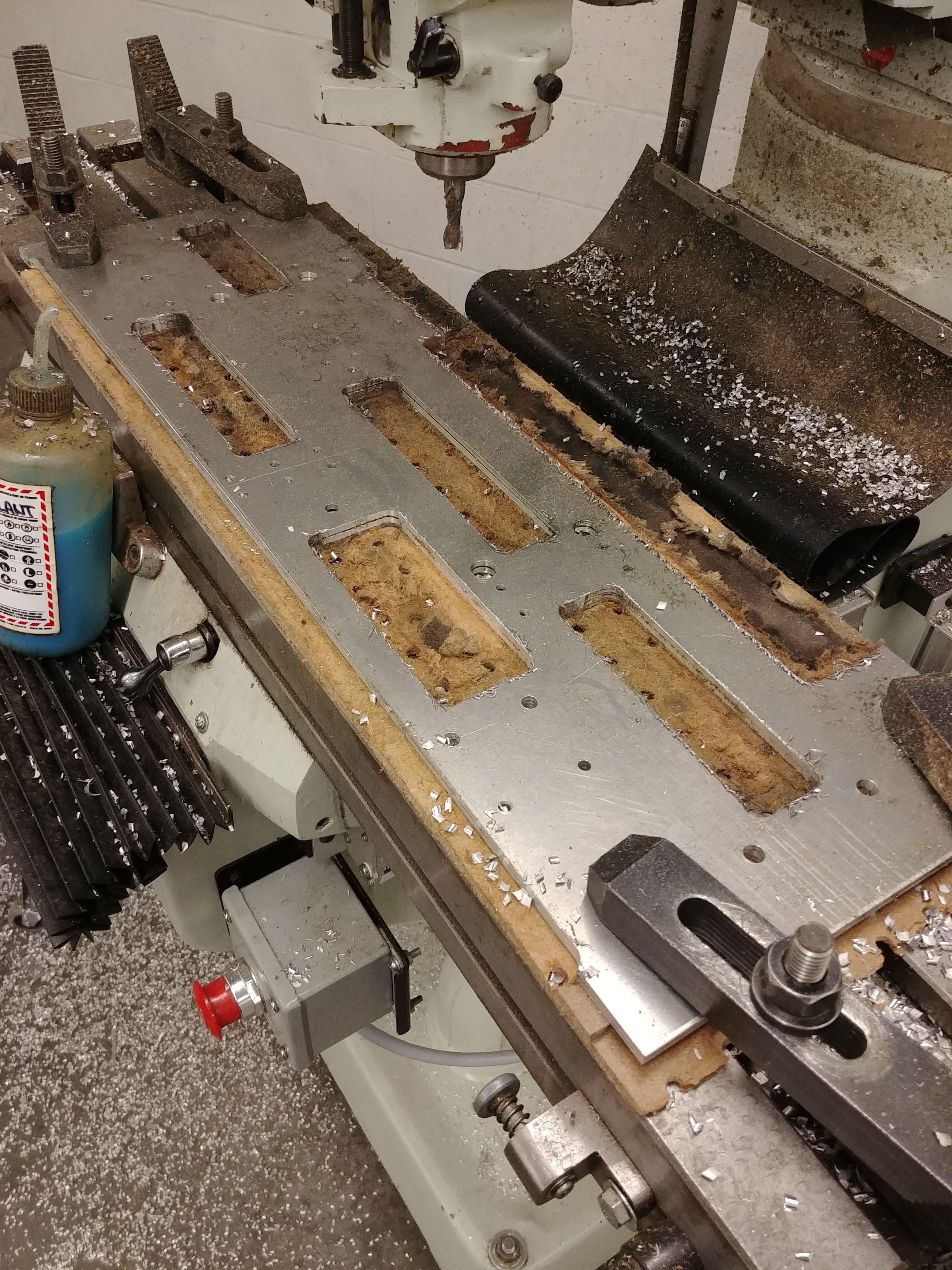
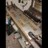
More Pictures!
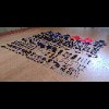
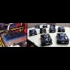
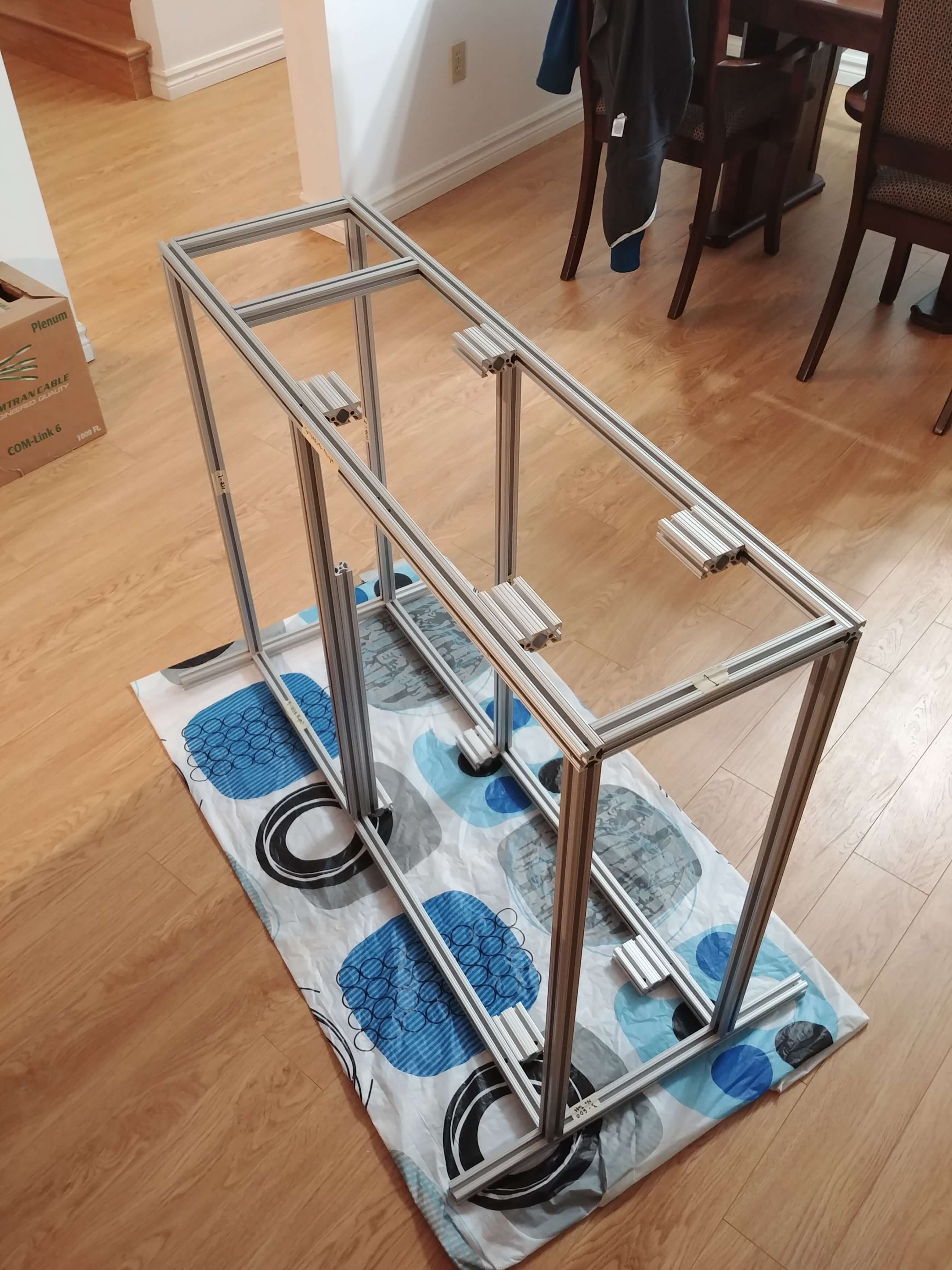
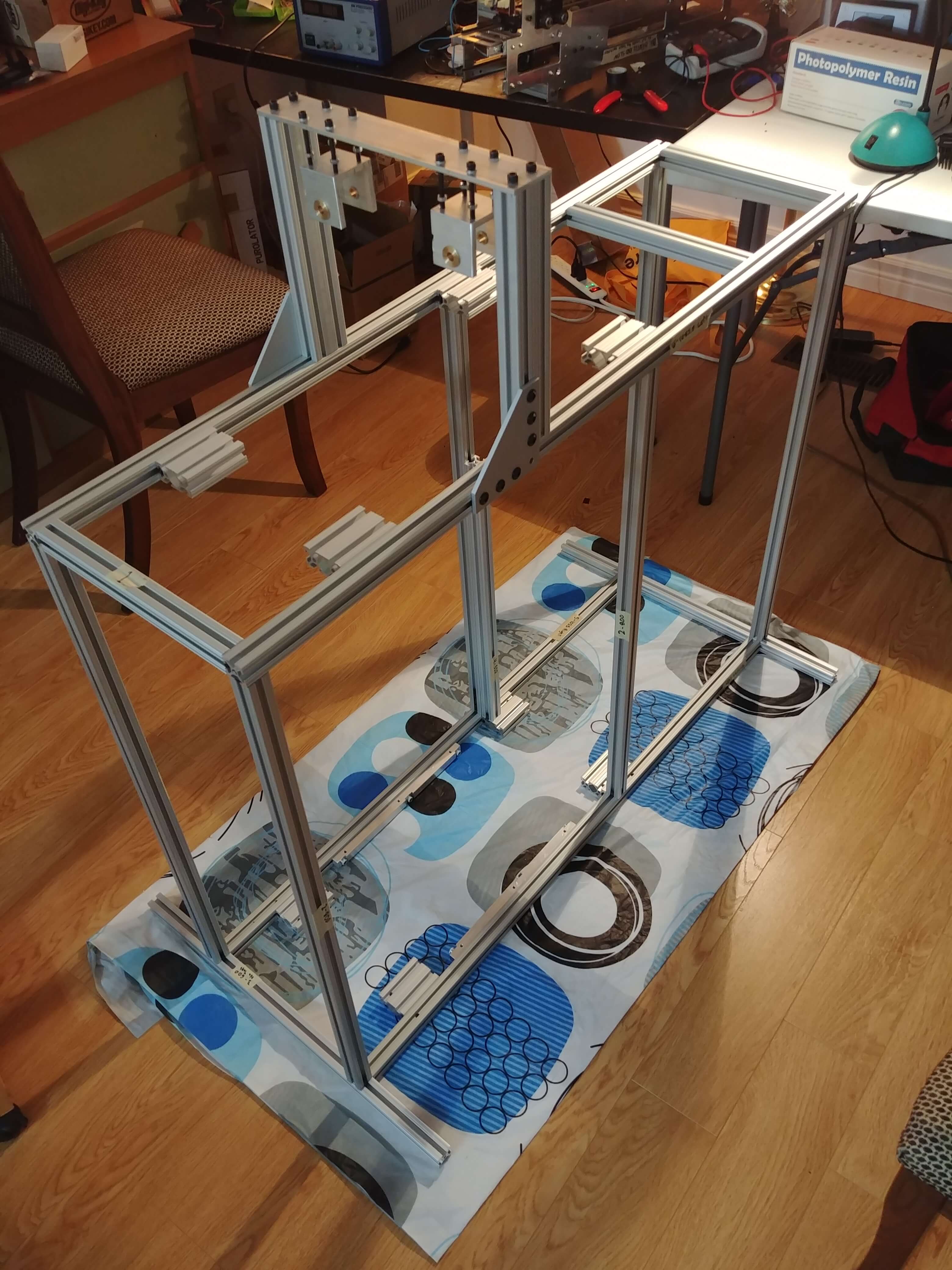
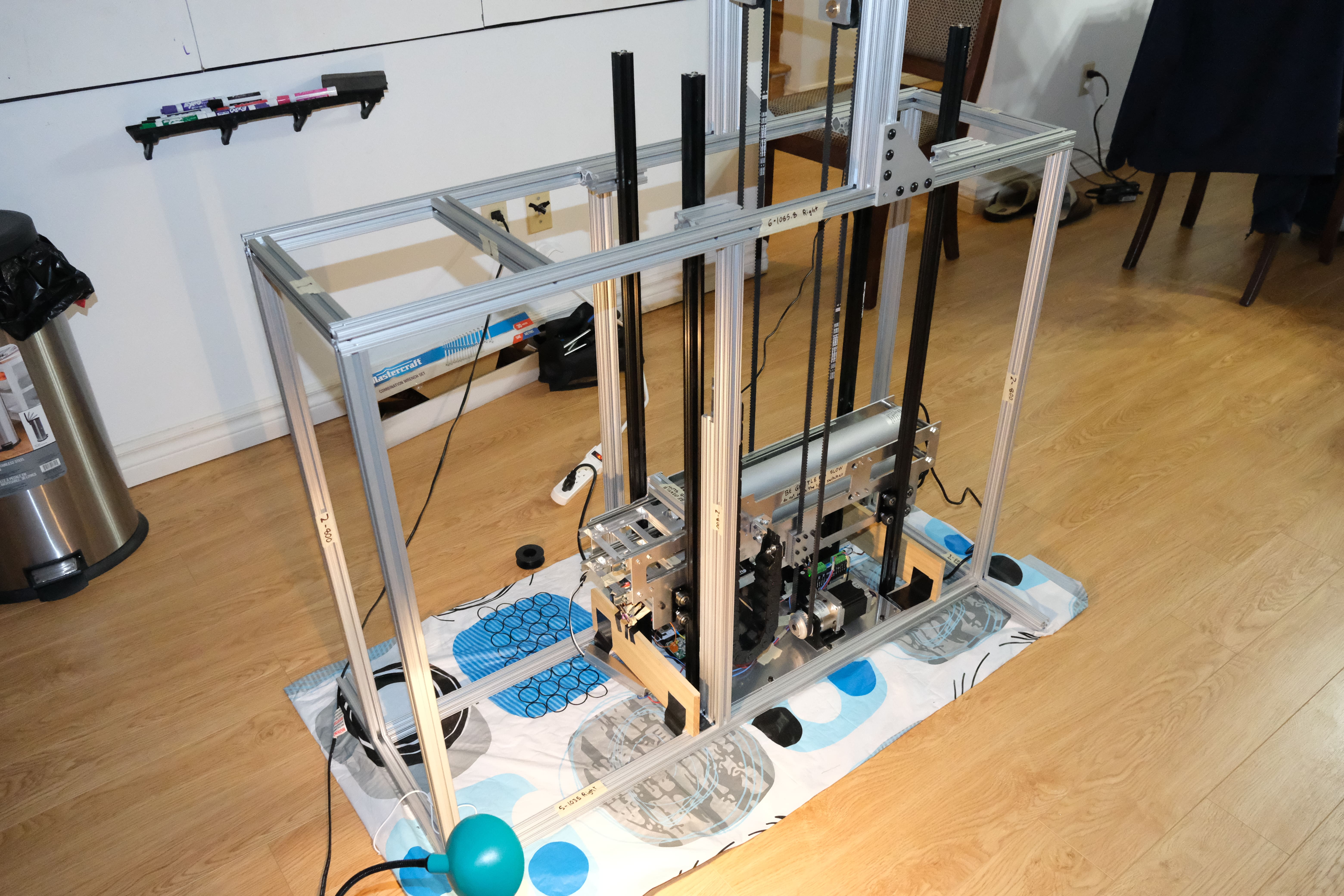
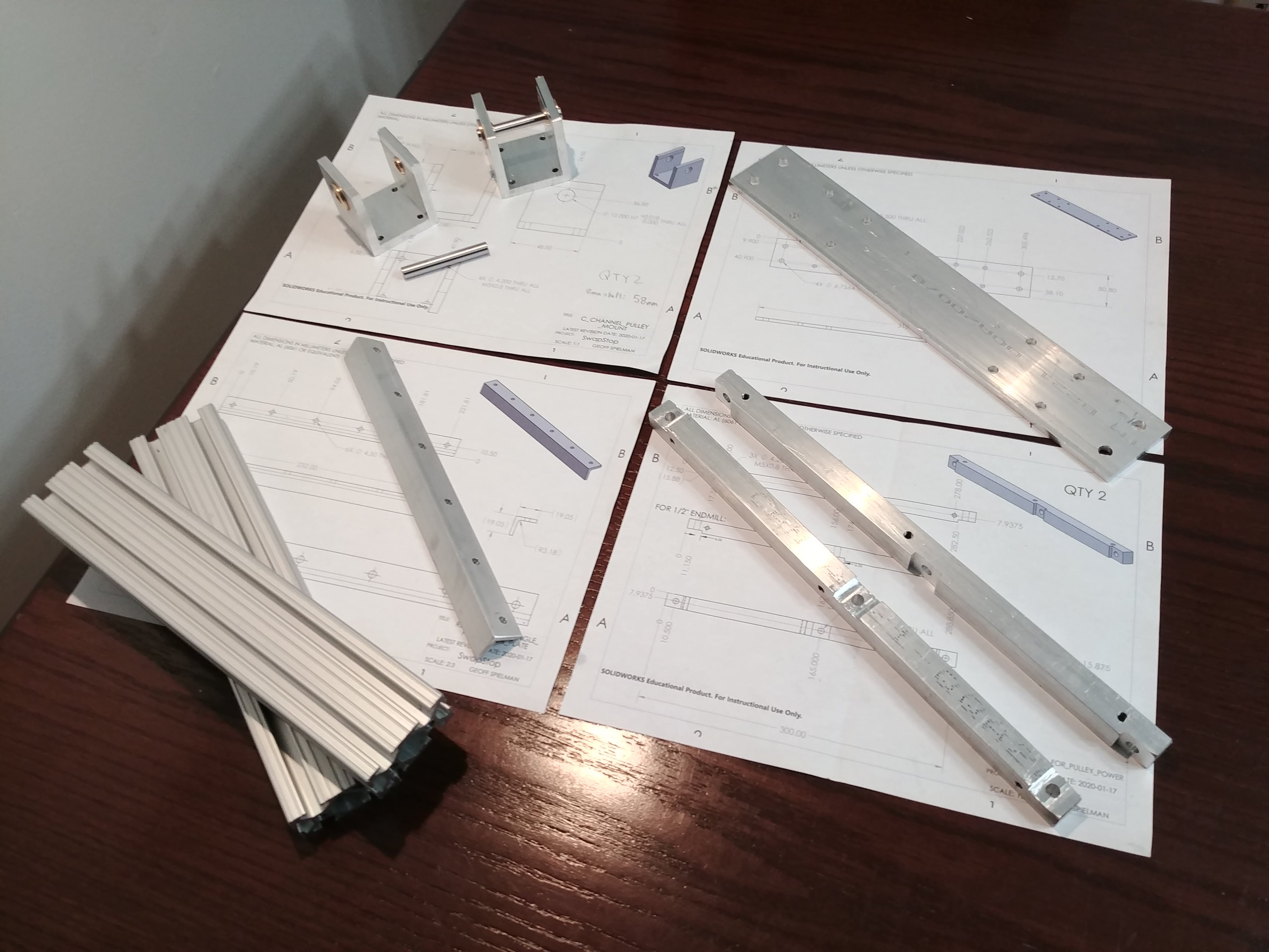
Here are some more pictures taken over the 8 months we spent designing, building, and integrating the project. I spent countless hours in the machine shop and at home running two of our personal 3D printers to make all the parts we needed.