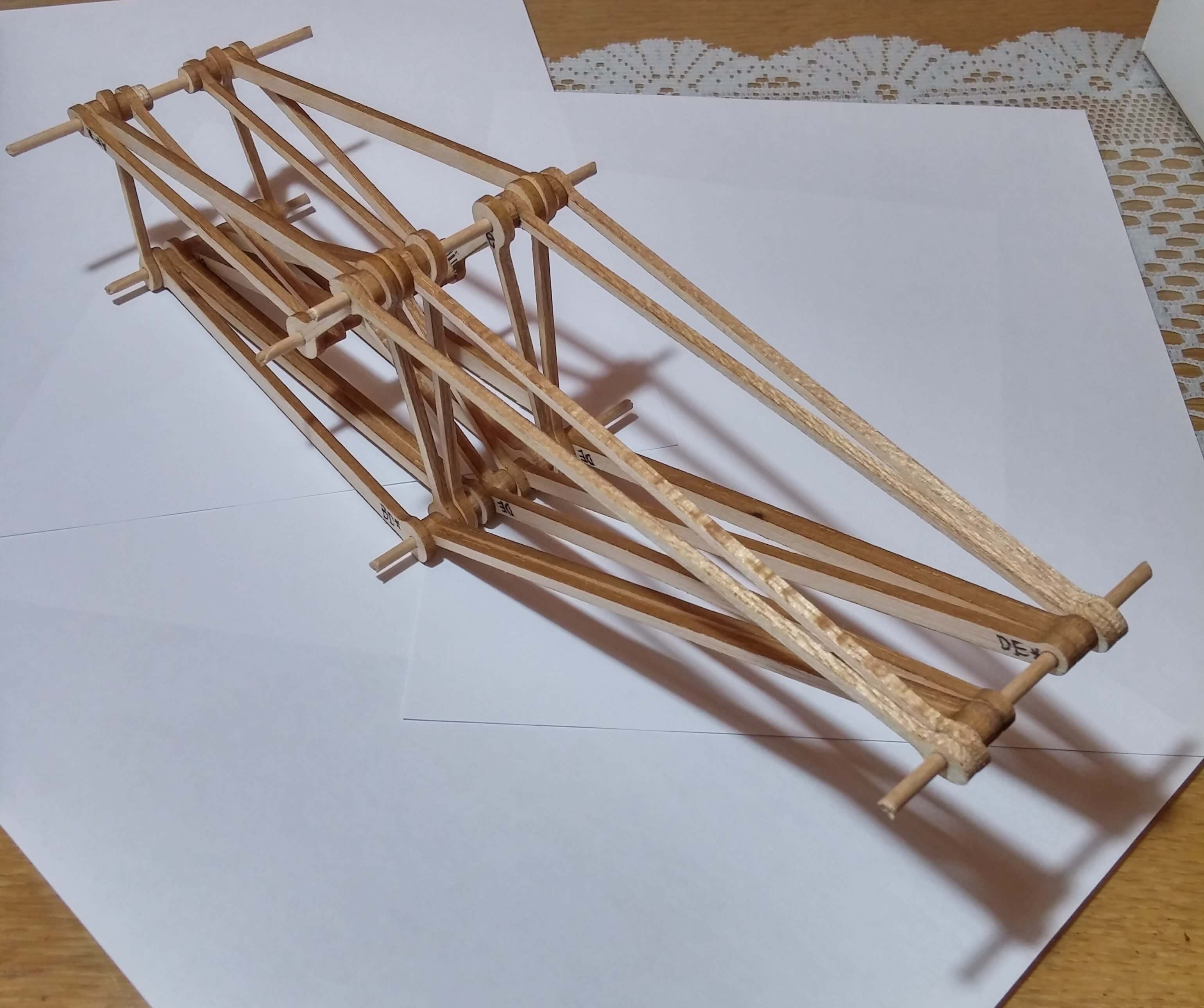
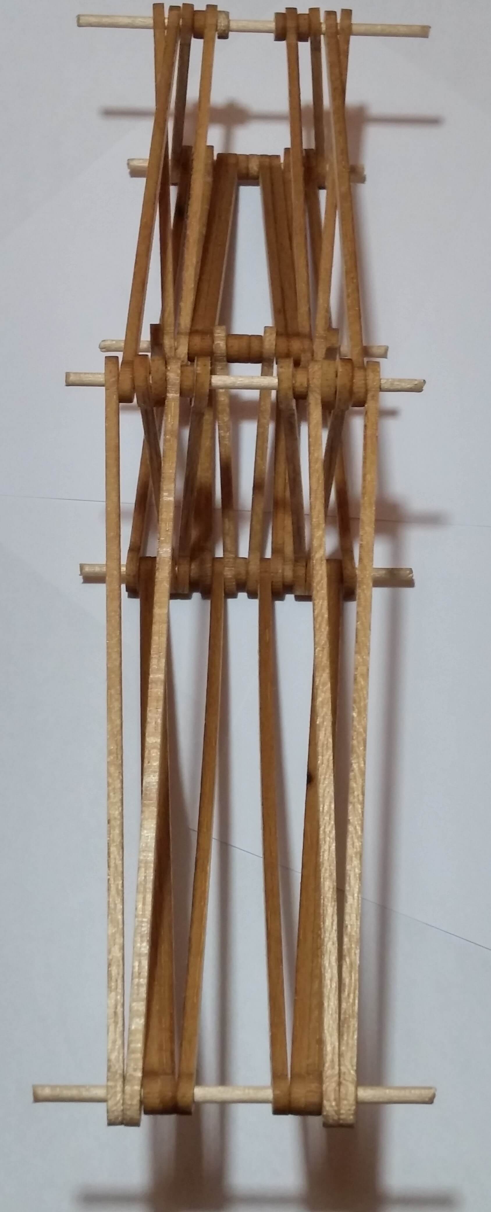
This is a cantilever truss that I worked with Will Clark and Tom Meredith to design and build.
We completed this project for our MODS (Mechanics of Deformable Solids) course in second year. The goal of the project was to design
a cantilever truss that was as strong and light as possible since each team’s score was determined by the load that their truss held
divided by the mass of their truss. Our truss held 183 times its weight.
The focus of the project was on the optimization of the truss design and performing a comprehensive stress and failure analysis.
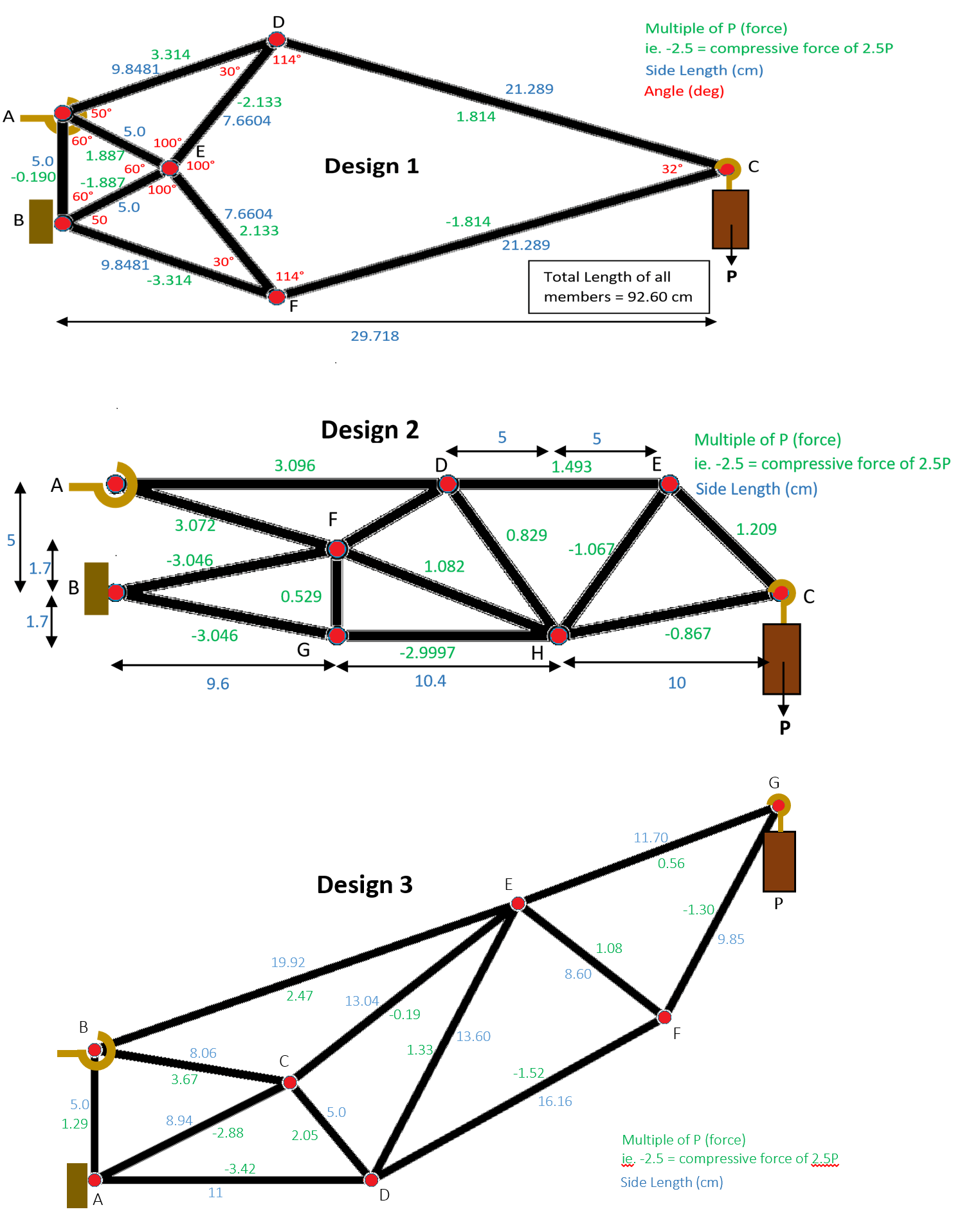
Our group started with 3 designs, selected the best one and optimized the equations for the portions of the load carried by each
member at each joint in order to finalize the 2D geometry of the design. Then we performed a precursory stress analysis to
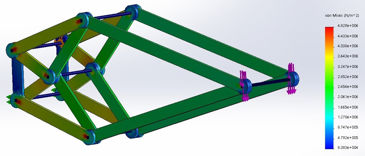
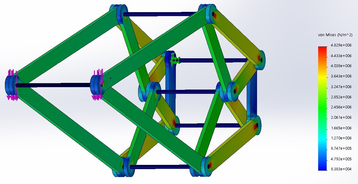
determine the required quantity and thickness of each member to complete the 3D design. I have always been interested in
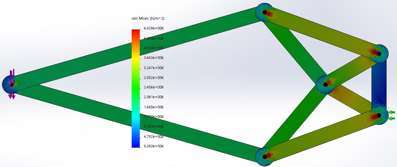
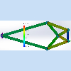
learning FEA in SolidWorks so as an aside I learned the basics and did a rough analysis on one of our earlier designs to
confirm our calculations.
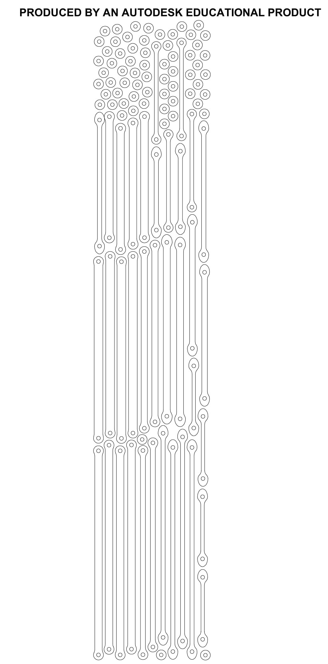
Once we had our preliminary design we drew all of the members in AutoCAD and used a laser cutter to cut the members out of sheets of
balsa wood. We tested our prototype and determined that buckling was our most significant problem since the truss bent off to the
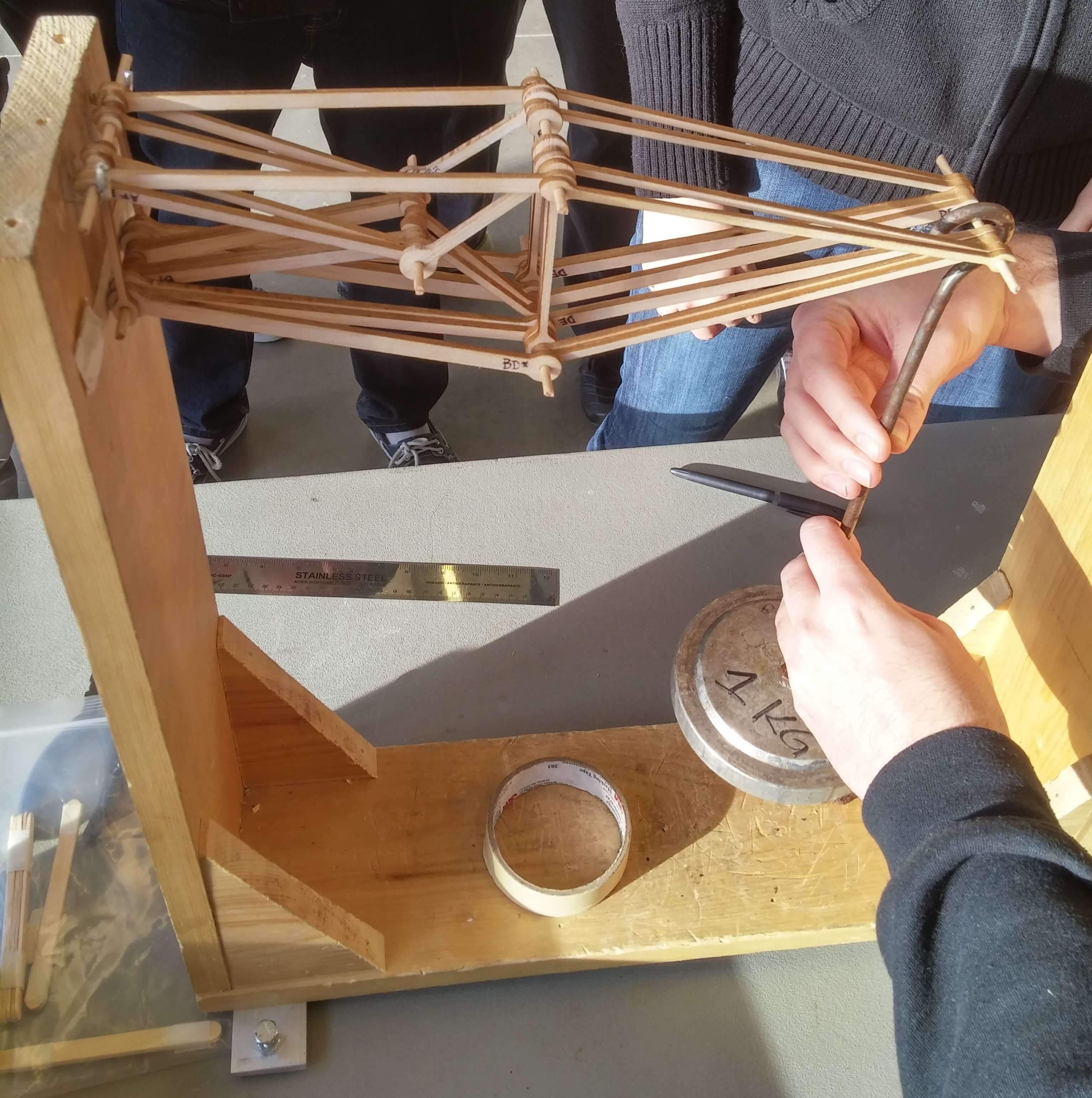
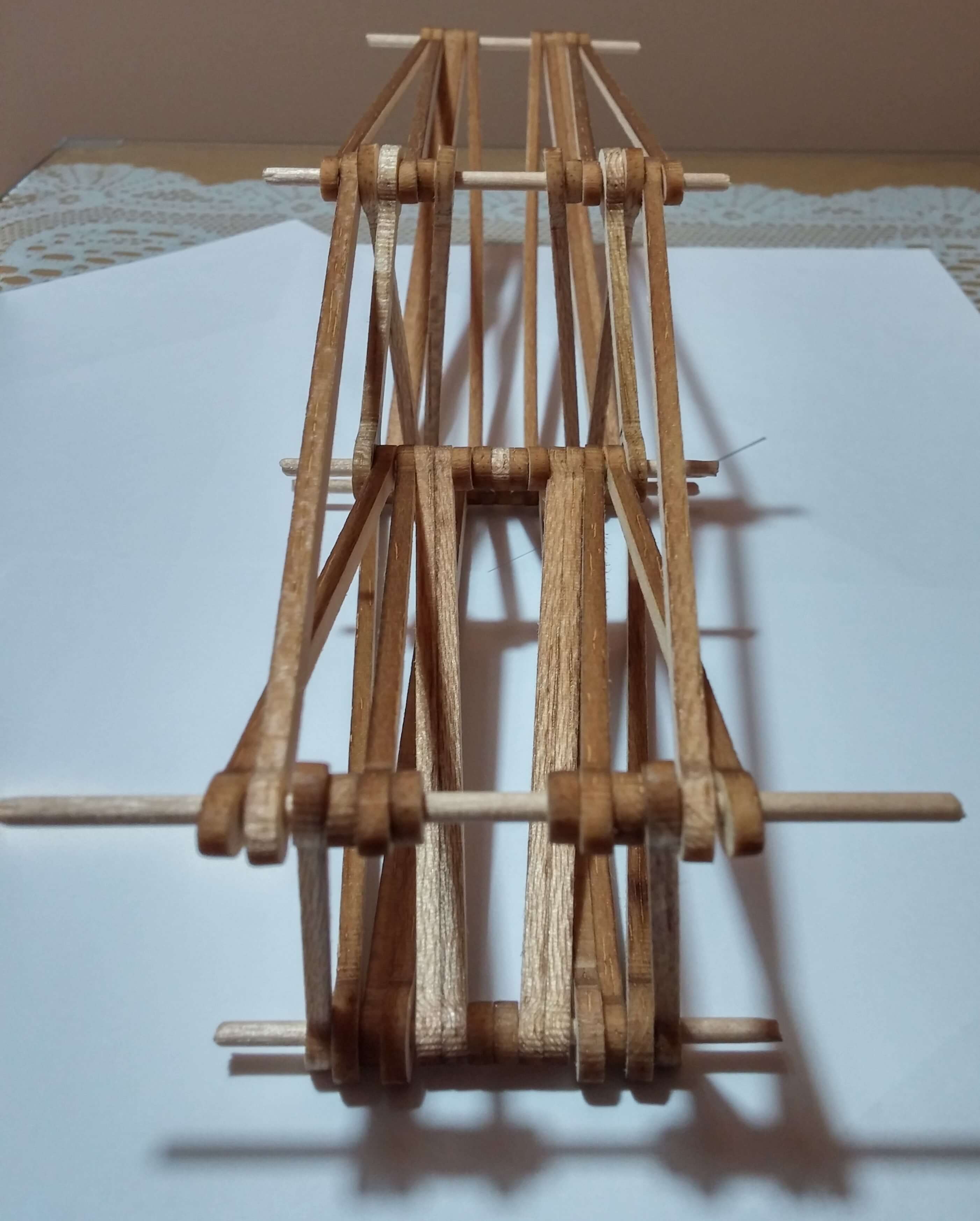
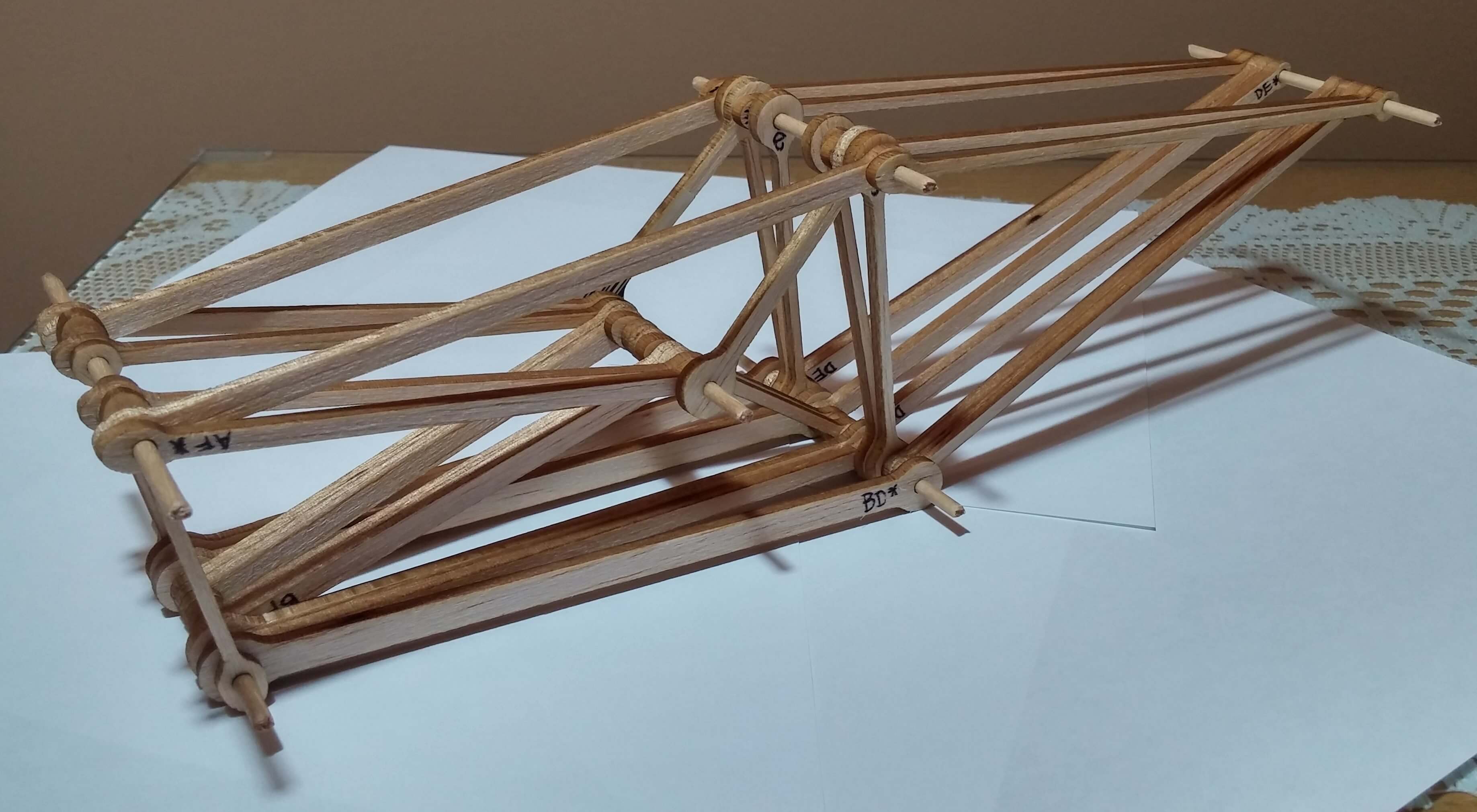
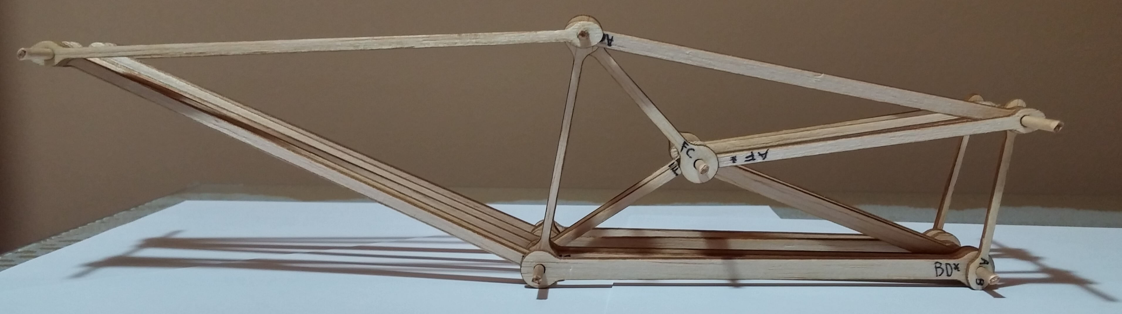
right or left under significant loading. We experimented with diagonal members to form triangles at each joint (see the 3D model
above) and after another iteration we finalized our design. Next, we performed a comprehensive failure analysis on the updated
truss where we investigated normal stress, tear out, bearing failure, buckling and shear stress and determined at what loading the
truss would fail. Using this information we made each member as thin as possible to increase our score. Below is a slow motion
video of the failure of our truss. The truss failed in 6 different places simultaneously which confirmed our calculations and
indicated that the design was thoroughly optimized.
These are a few pictues of the FEA analysis, the truss itself, the AutoCAD drawing of all members nested for laser cutting, and our 3 original designs.