In my 2A semester at Waterloo I had to create a sensor from first principles for my Stats course, Experimental Measurement
and Statistical Analysis (I didn’t quite get the course title right in the video, my apologies). I worked with three other
mechatronics engineering students (Will Clark, Tom Meredith and Will Thibault) to
create a distance sensor. The focus of the project was on designing from first principles, going through the calibration
process using know standards and coming up with an uncertainty value for the sensor. We determined our sensor had a maximum
uncertainty of +/- 1.5 mm but was generally well within +/- 1 mm.
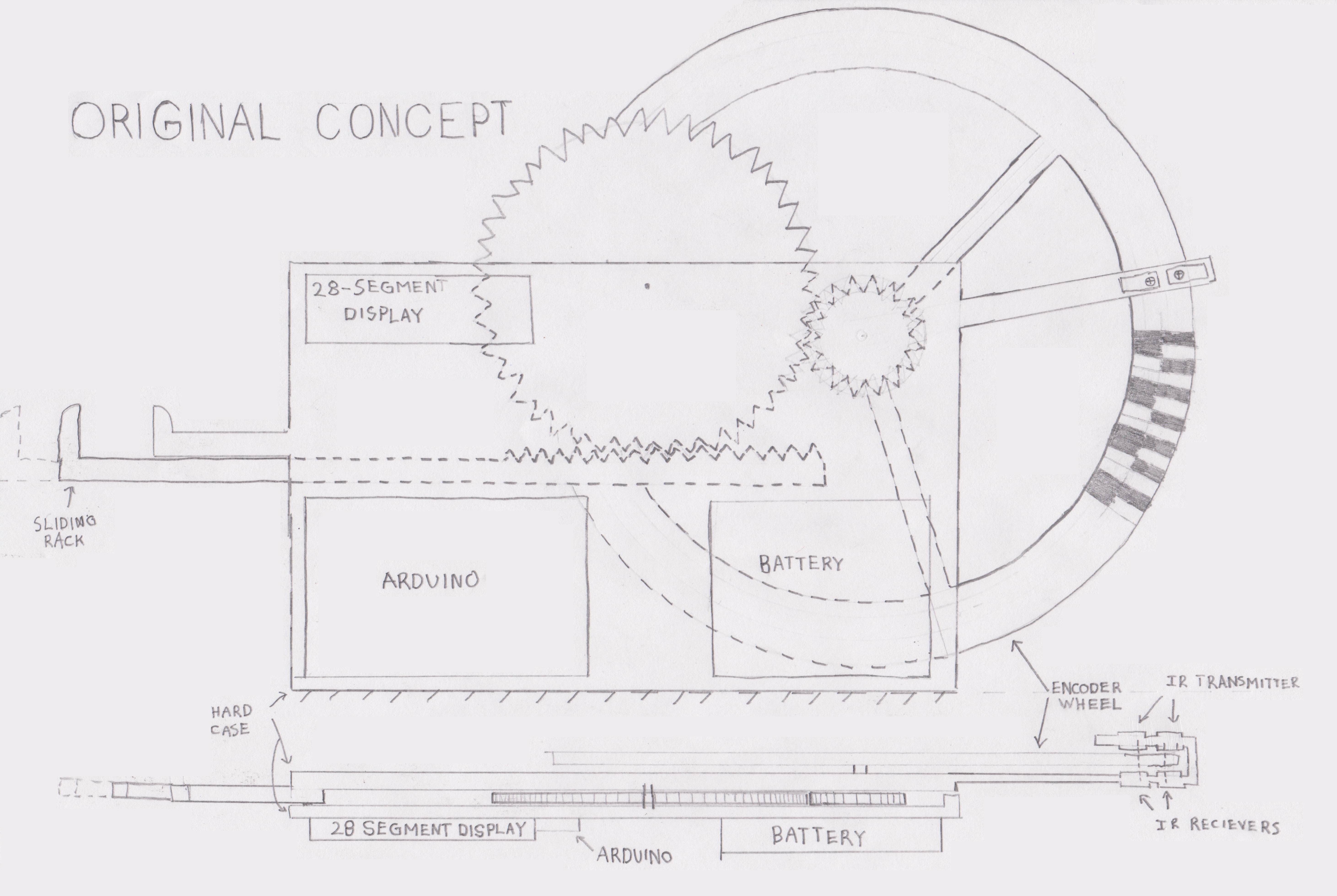
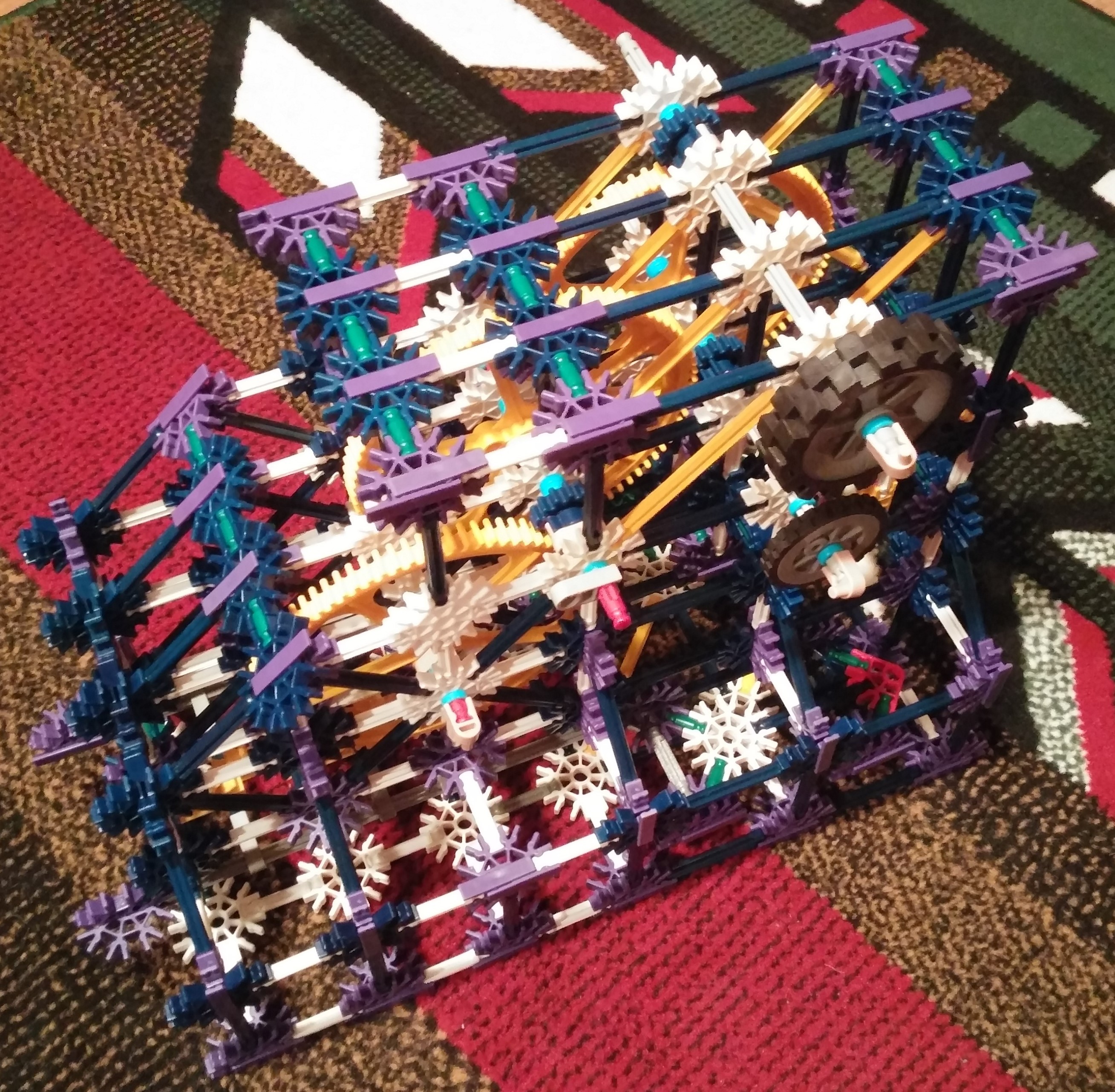
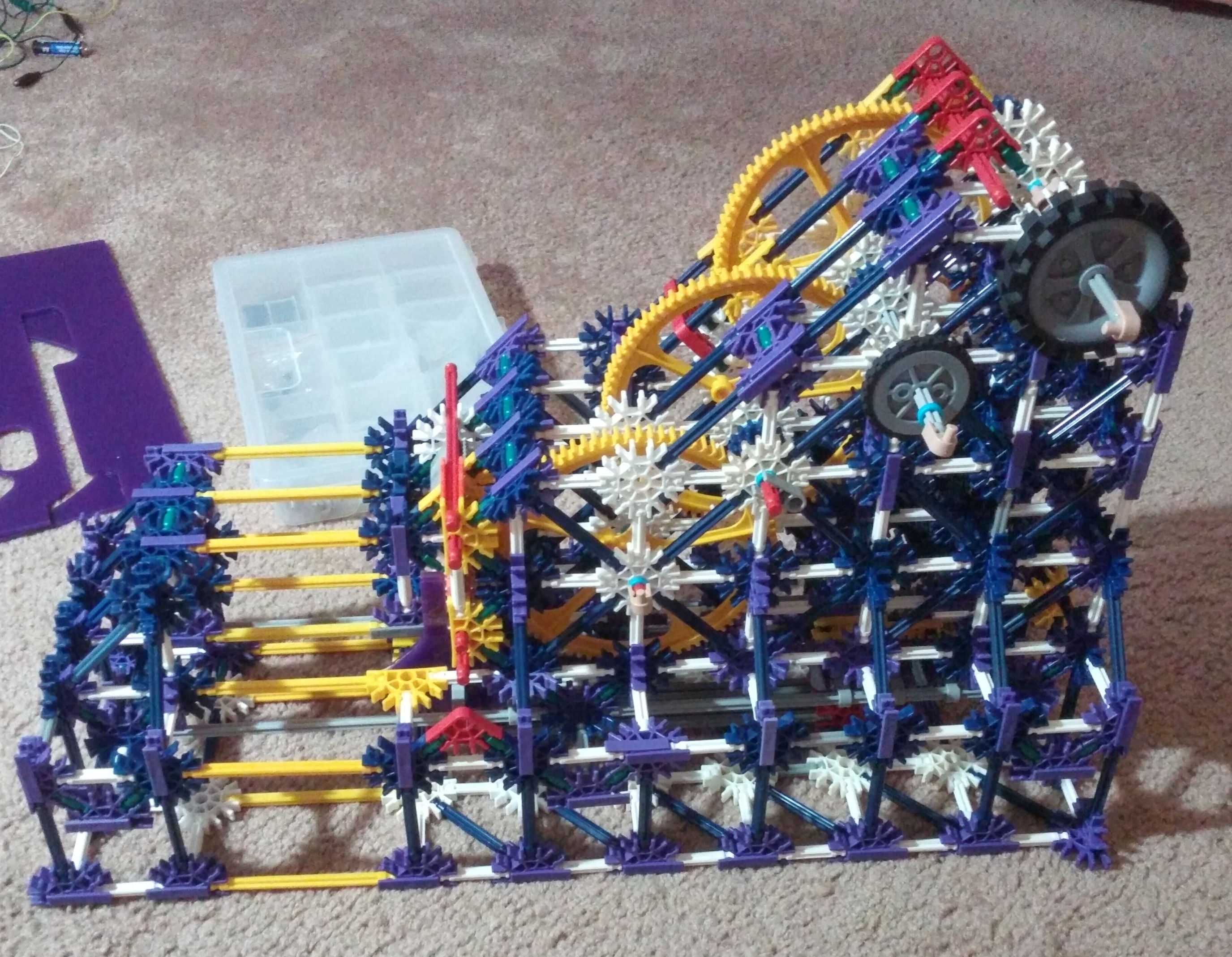
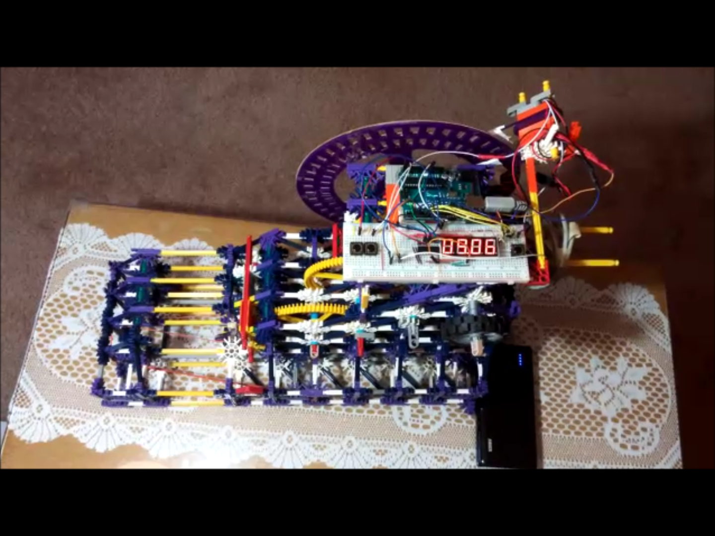
The functionality of the sensor is similar to a pair of digital calipers; it has two Jaws, one of which is stationary while
the other is on a rack and pinion system which is moved by rotating a tire near the top of the device. Prior to taking a
measurement, you close the jaws to zero the device and then open the jaws and clamp them around the object to be measured.
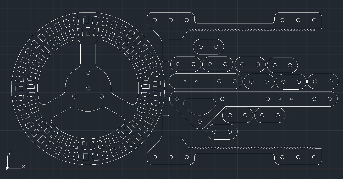
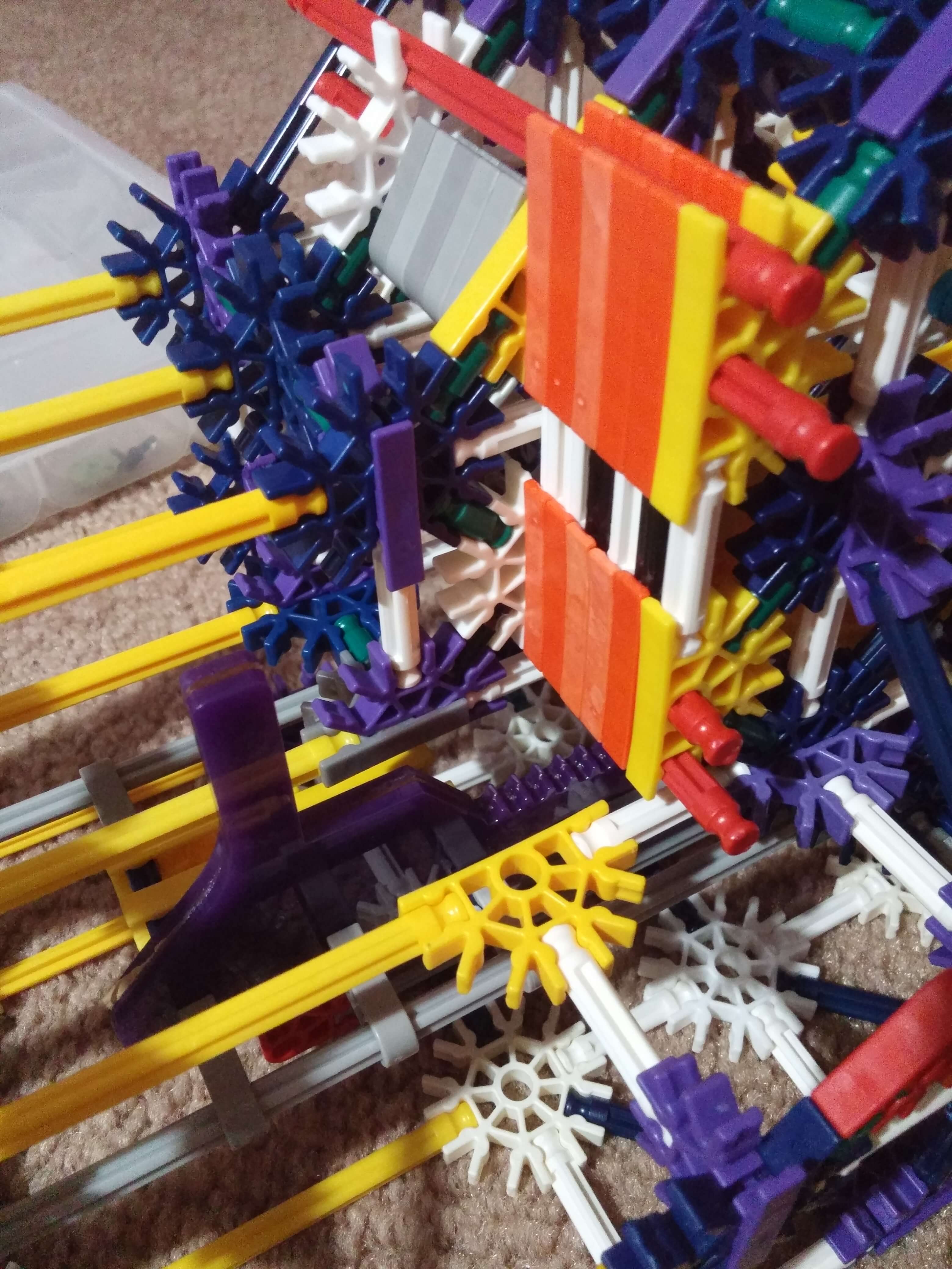
Most of the device is built out of K’nex but we had to make drawings in AutoCAD and laser cut a few parts including the
encoder wheel and a rack to mesh with the K’nex pinion.
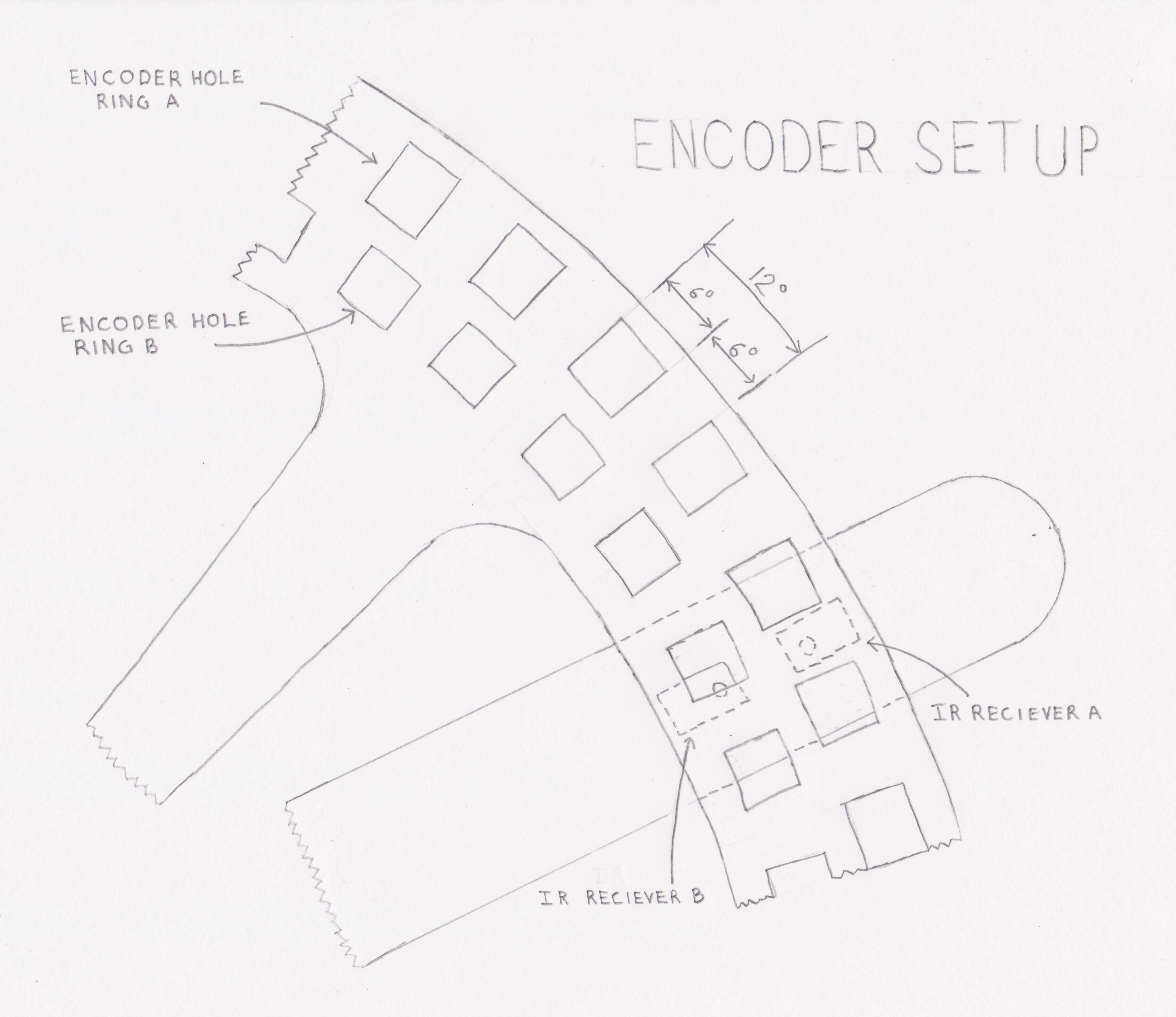
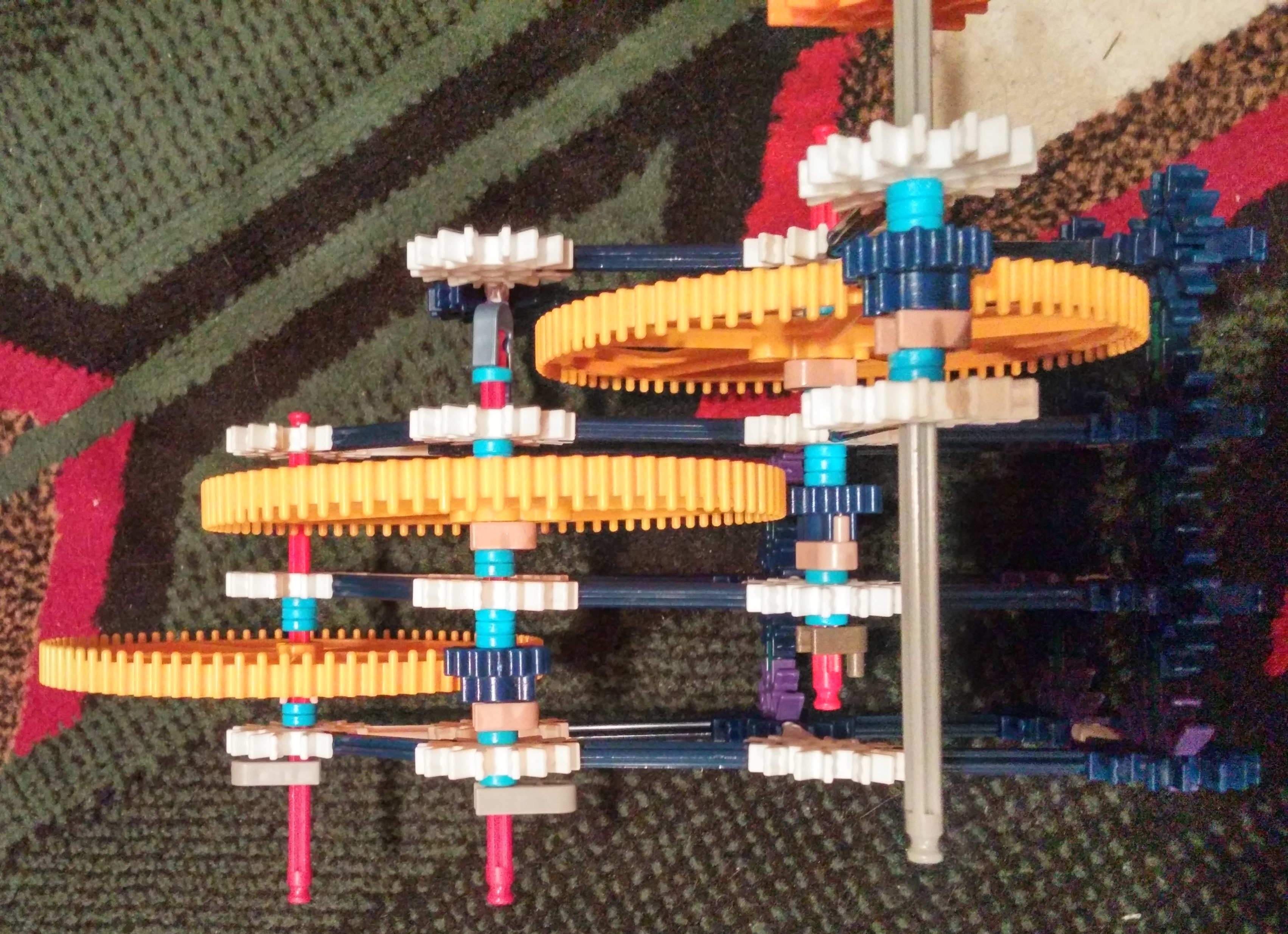
The design implements a series of 3 gear reductions that provide reduction ratio of 1:43 encoder wheel to the pinion driving
the rack, allowing us to register far more counts per distance increment. We chose to build the incremental encoder wheel
out of cardboard (to block the infrared light) and acrylic (for strength) with the inner ring of holes offset from the outer
ring by half the width of a hole (see pictures). We used infrared break beam sensors with an emitter on one side of the wheel
and two receivers on the other side so that when we detect a rising edge on the outer ring we could determine which
direction the wheel was spinning based on if the inner ring receiver was blocked or not. We used interrupts on the Arduino to
detect rising edges and either incremented or decremented an internal counter based on the direction of rotation.
From there we multiplied the counter by our conversion factor which was obtained through the calibration process to get from
counts to millimeters and we output the distance to a seven segment display (using shift registers to accommodate multiple
digits). Below I’ve included a few photos of the device at various stages of development, the original concept sketches and
the AutoCAD drawings of the parts for laser cutting.