Science Module for 2018 Mars Rover
Purpose of Module
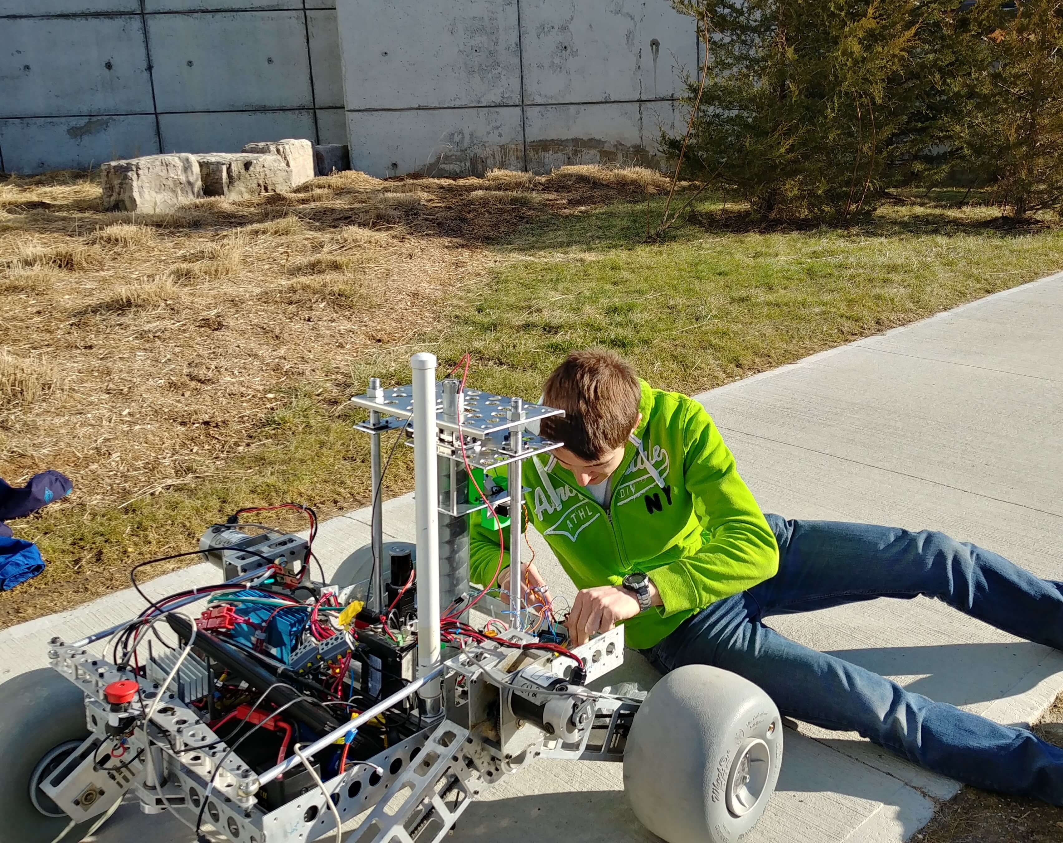
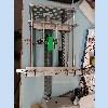
For the ‘science cache’ task of the University Rover Challenge , teams are required to collect soil samples from 10 cm below the surface and analyze their ability to support life. The module is capable of drilling down 20 cm (more on this later) and measuring the soil’s temperature, humidity and electrical conductivity on board. In addition, the module can store a sample in a sealed container on board and return it to the base station for further analysis. For this task the arm module is removed and the science module takes its place on the front of the rover, as shown below.
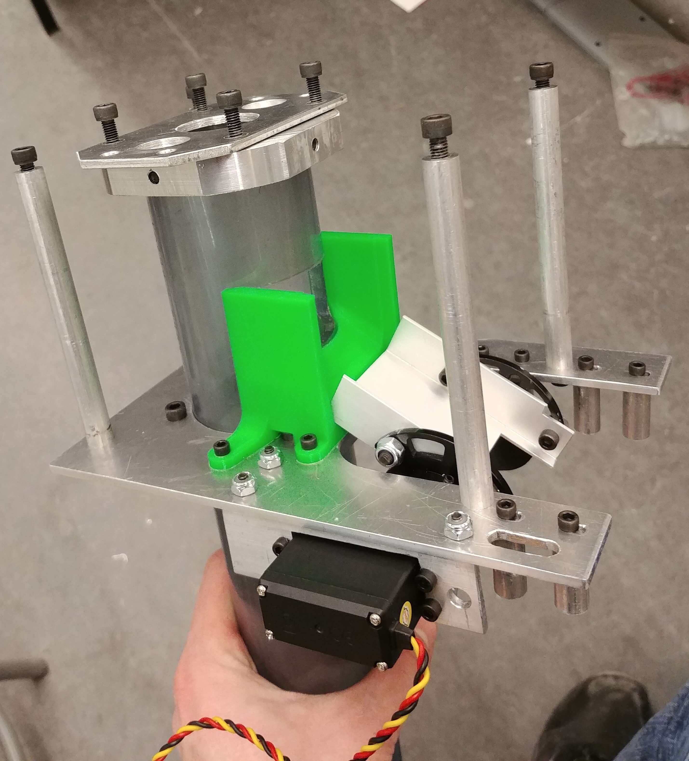
Functional Overview of Module
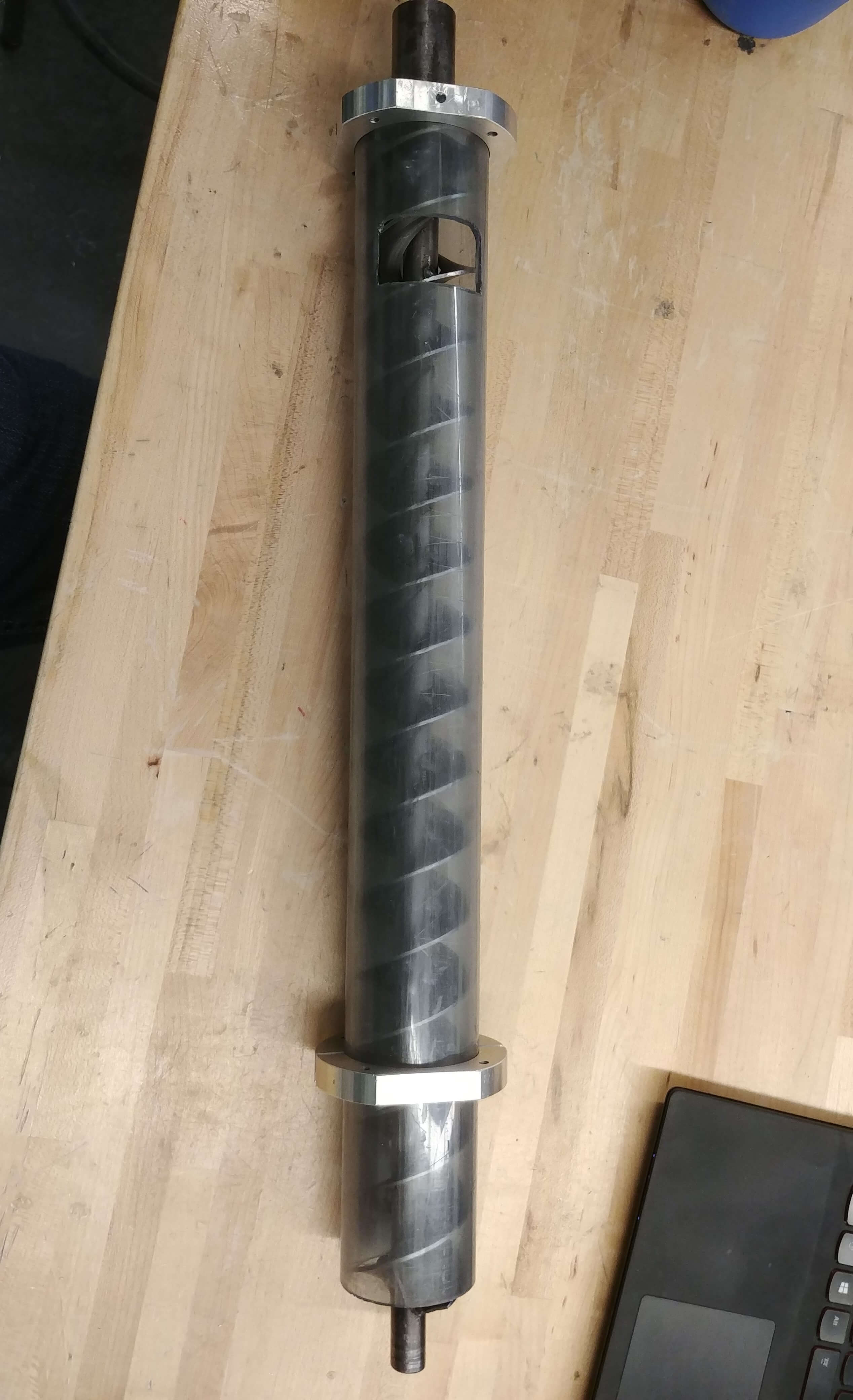
After researching various soil extraction methods, based on the geology of the Utah desert (where the competition is held) I selected an earth auger.
A custom-made auger was generously donated to the team by Greg Niewold from Power Planter , an auger company I
can’t recommend highly enough. The auger features two starts which provides more balanced loading and reduces wear on the auger sheath and a significantly
reduced pitch to prevent the loose, dry soil from sliding back down the auger.
To guarantee that the soil sample collected is from below 10 cm we run the auger in ‘bypass mode’ (discarding all extracted soil) until we reach a depth of
15 cm, then drill another 5 cm in ‘collect mode’. This way we can be confident that all soil reaching the top of the auger chamber came from below 10 cm.
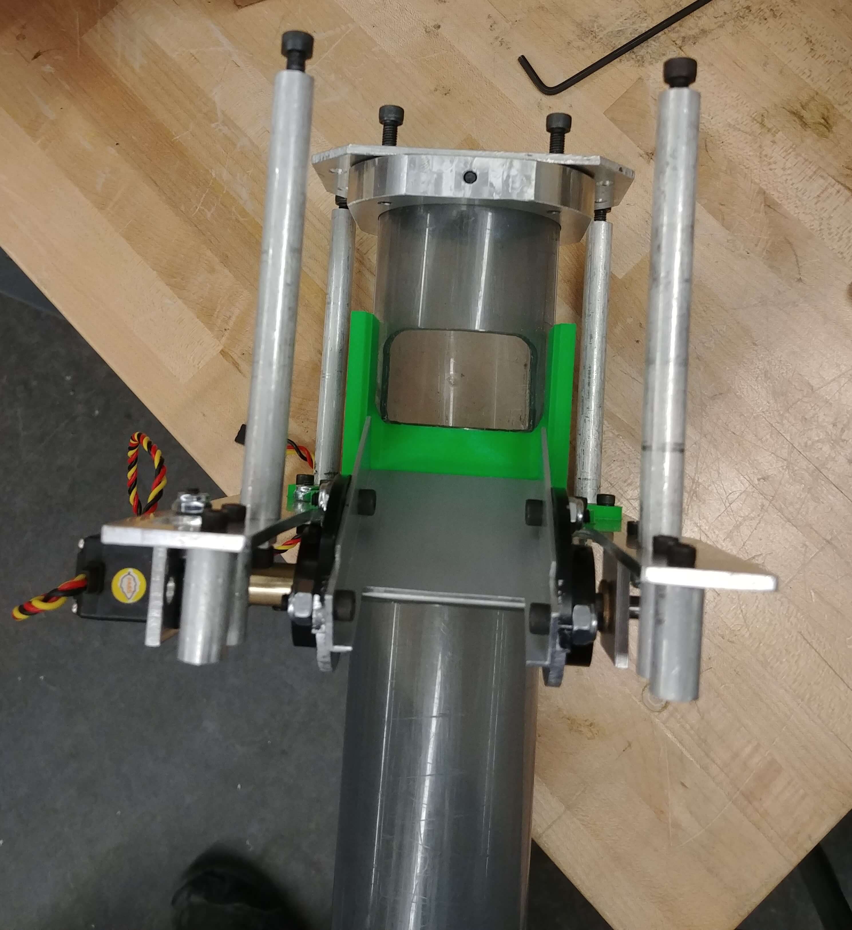
To switch between modes the C channel that extends from the auger sheath to the collection container can be rotated since it is attached to servo motor with
high holding torque. In ‘collect mode’ the channel acts as ramp from the auger sheath to the sample container, but in bypass mode it swings forward and acts
as the lid for the sample container, pressing up against a rubber seal (not installed yet in gif) to isolate the sample.
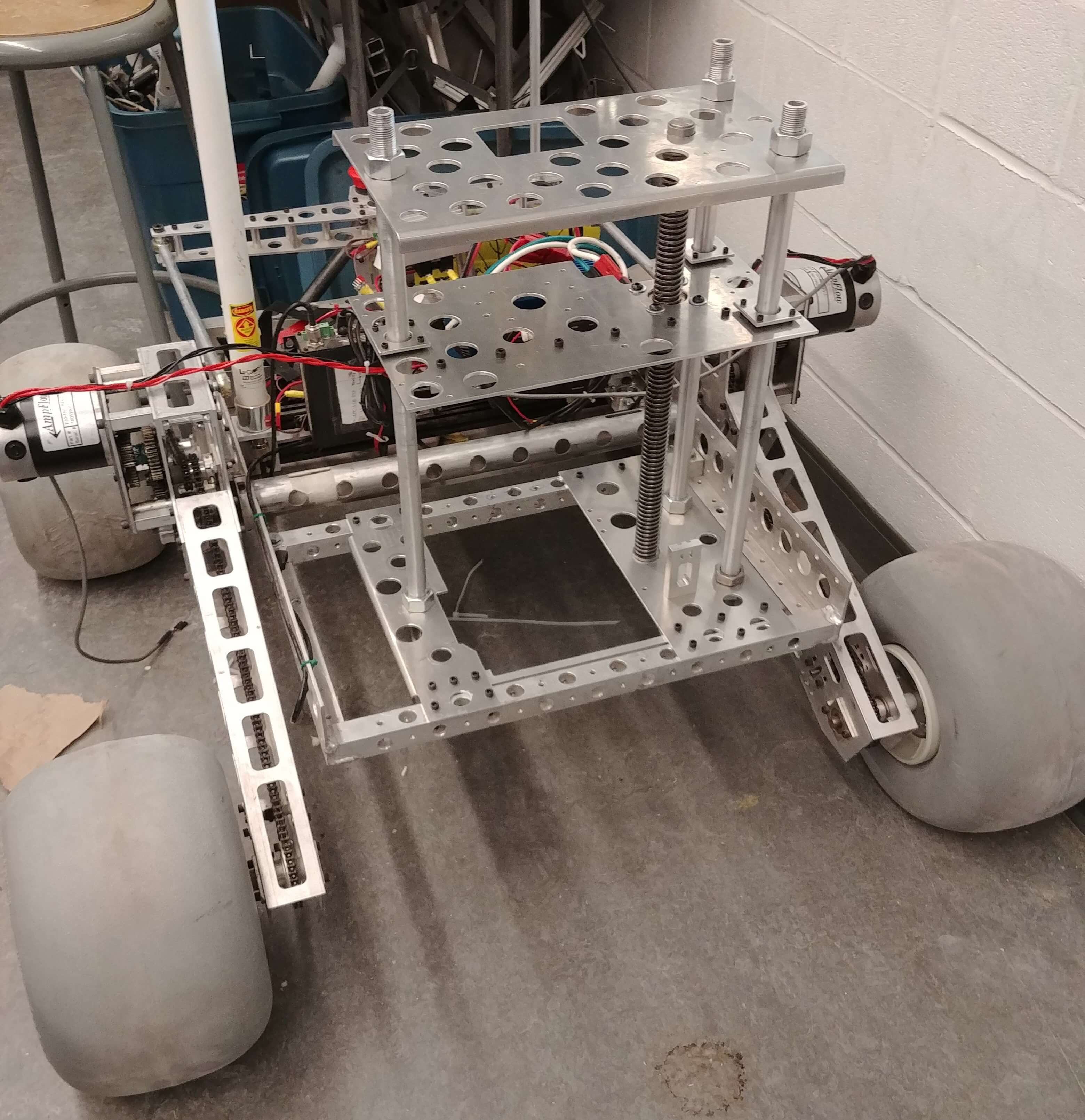
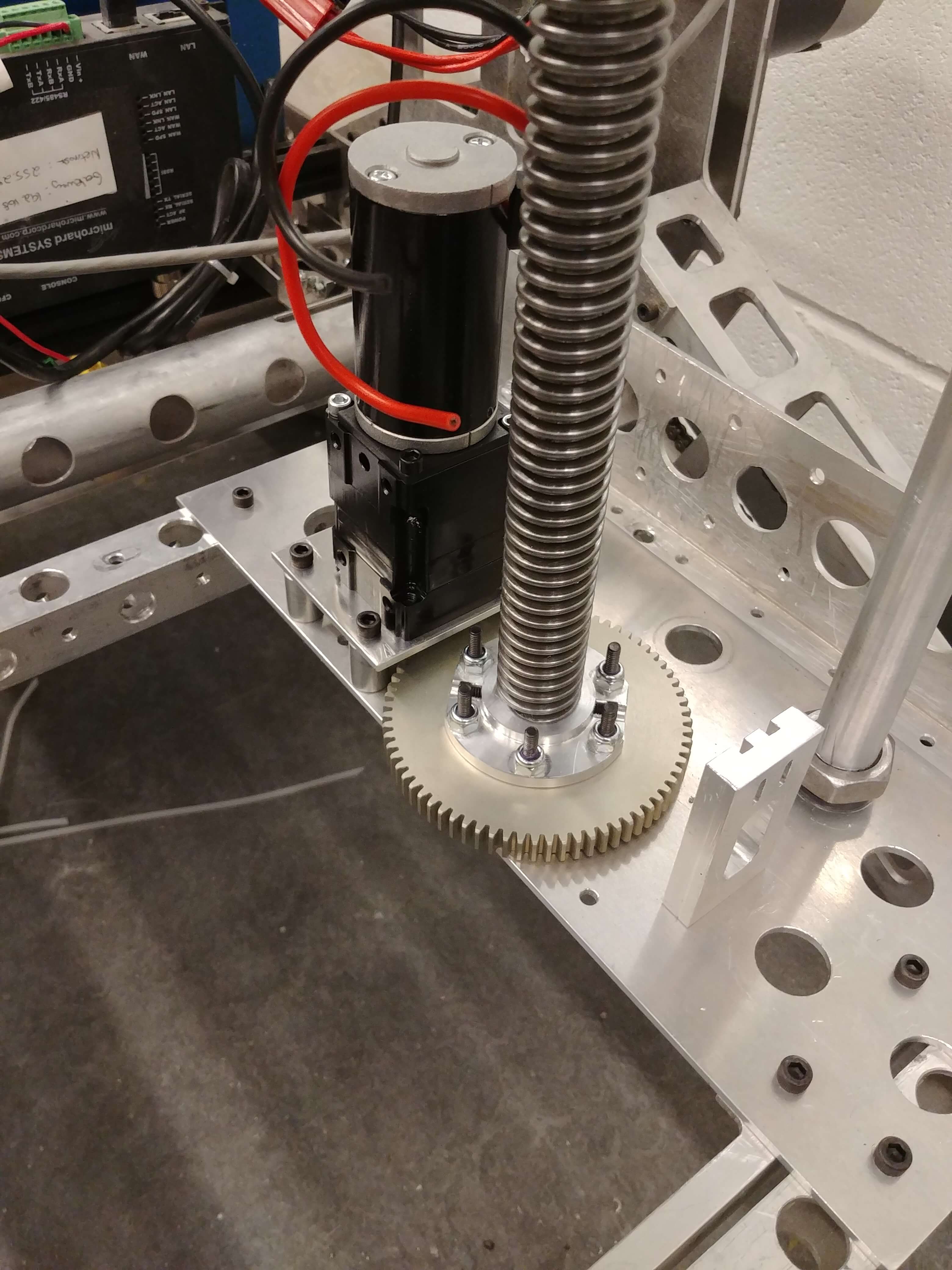
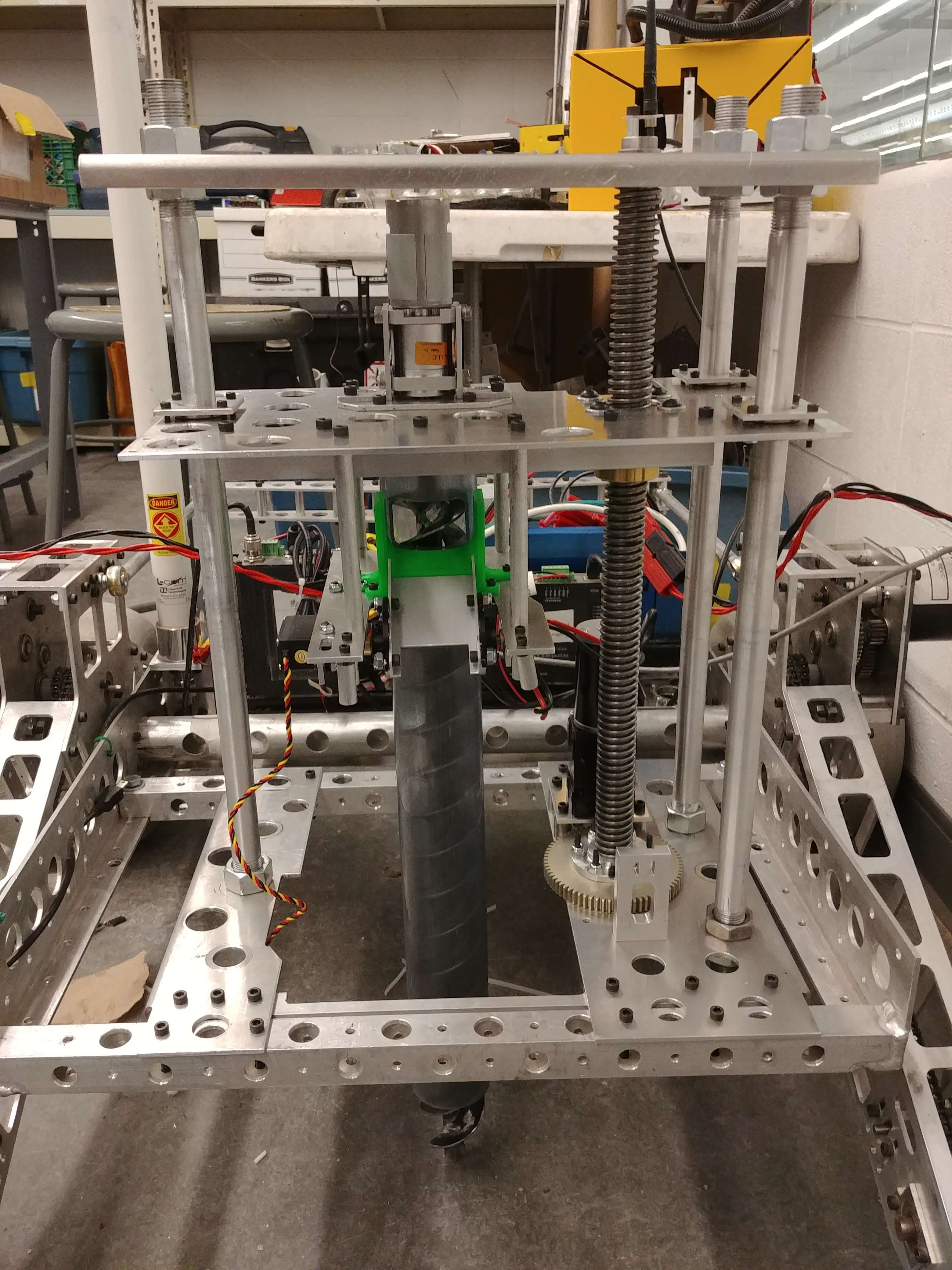
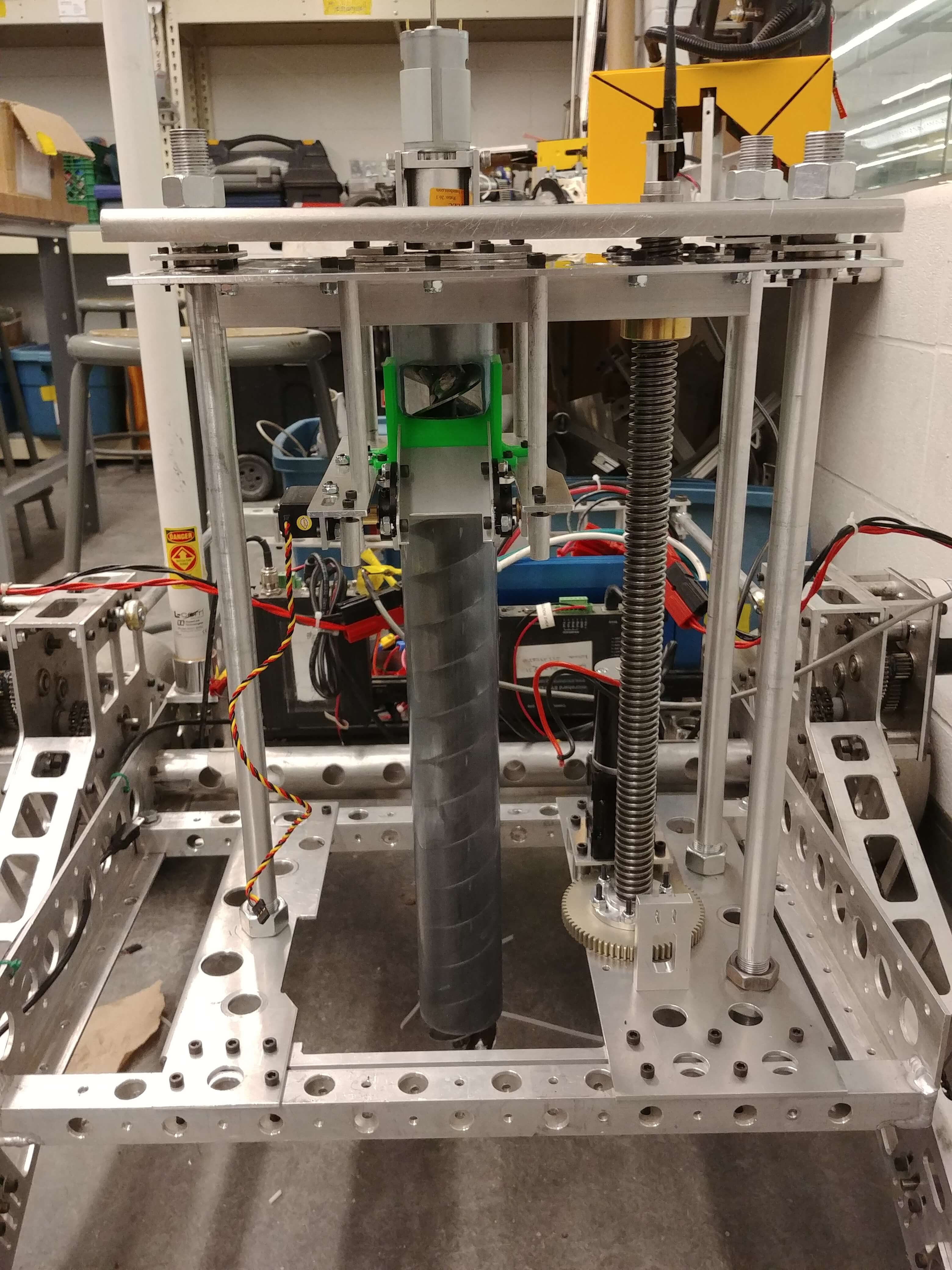
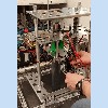
The elevator platform attached to the auger is translated via a lead screw driven from the bottom of the module (to keep our center of gravity low). I used a
BAG DC motor with an integrated encoder so that we’ll know where the platform is (and thus the depth of the auger) at all times. You’ll notice many holes all
over the module. Although most are for weight reduction, there are three holes along the left and right sides of the top two plates and corresponding holes
in the two bottom plates that all align vertically. This allowed us to try different support rod positions and combinations since it was difficult to determine
in the design phase which configuration would lead to less chatter as the elevator plate went up and down. My original plan was to have two support rods on the
left and only one on the right, but after some experimenting we decided the one you see in the pictures and CAD was optimal.
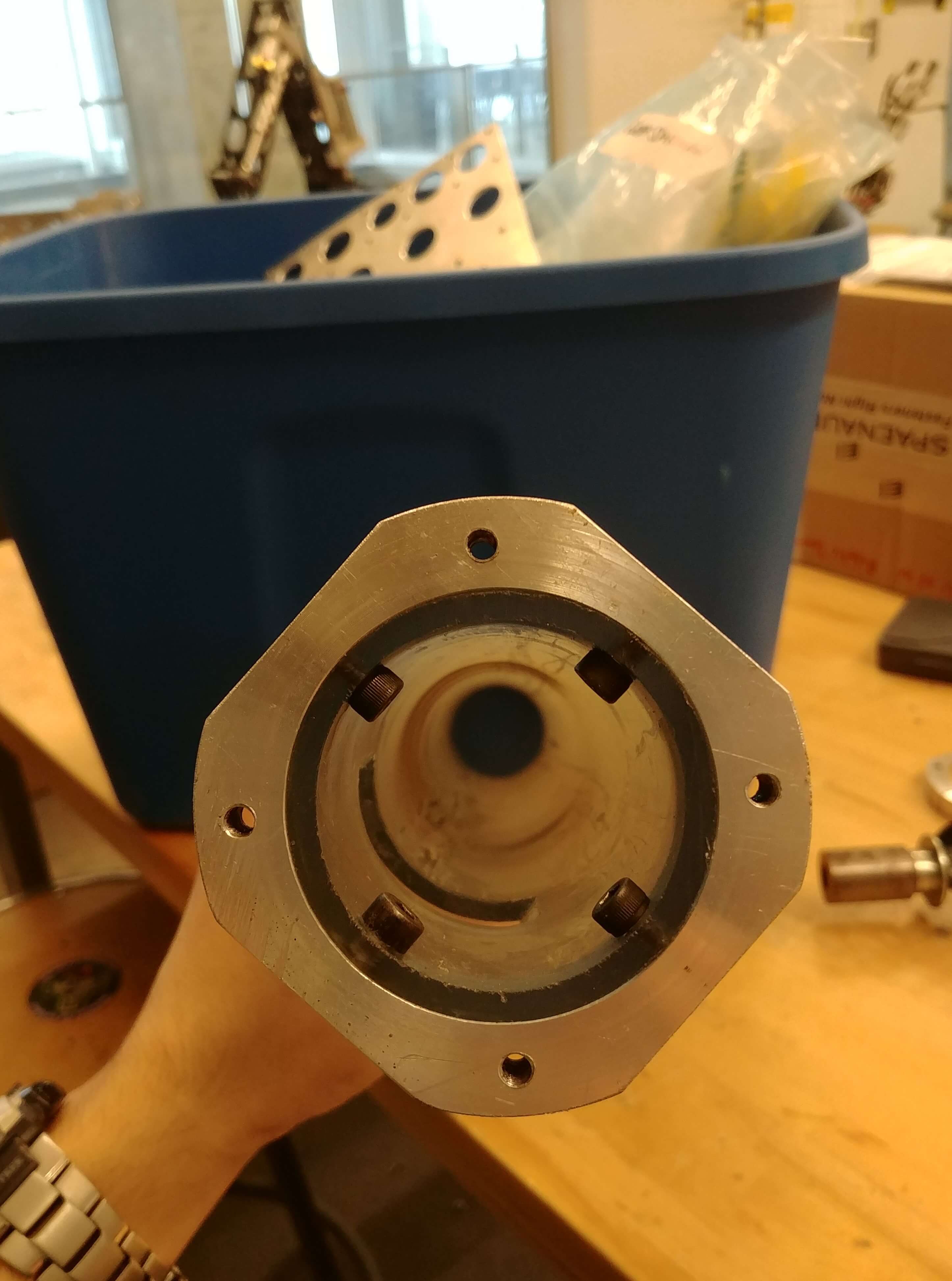
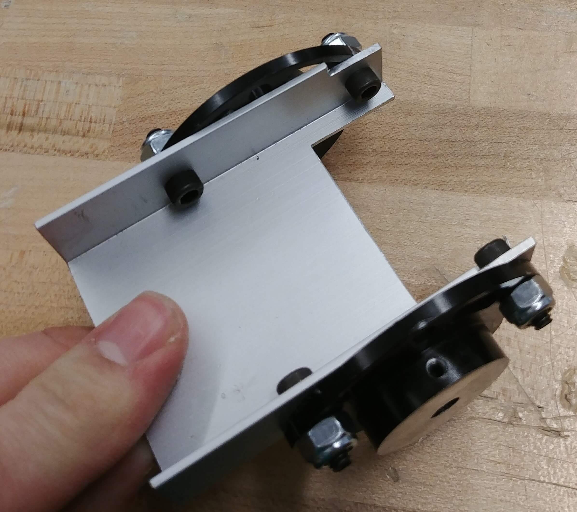
Lead Screw Driving Subassembly
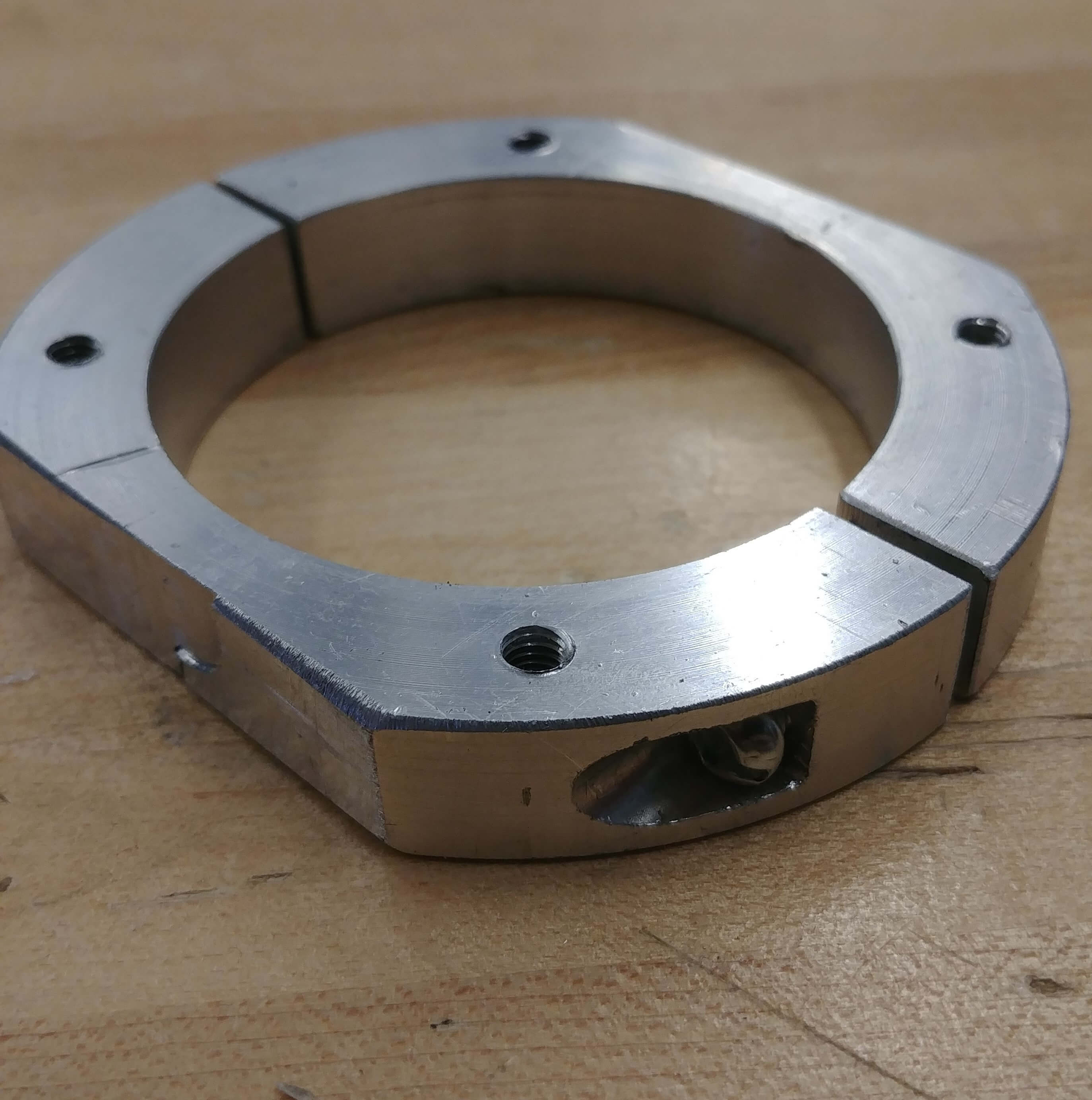
The mechanical subsystem at the base of the leadscrew is one of the most difficult design tasks I’ve faced and one of the designs I’m most proud of. Since we were reusing a leadscrew we already had, (lead screws are expensive and our budget is tight) I only had 1 inch of shaft to work with.
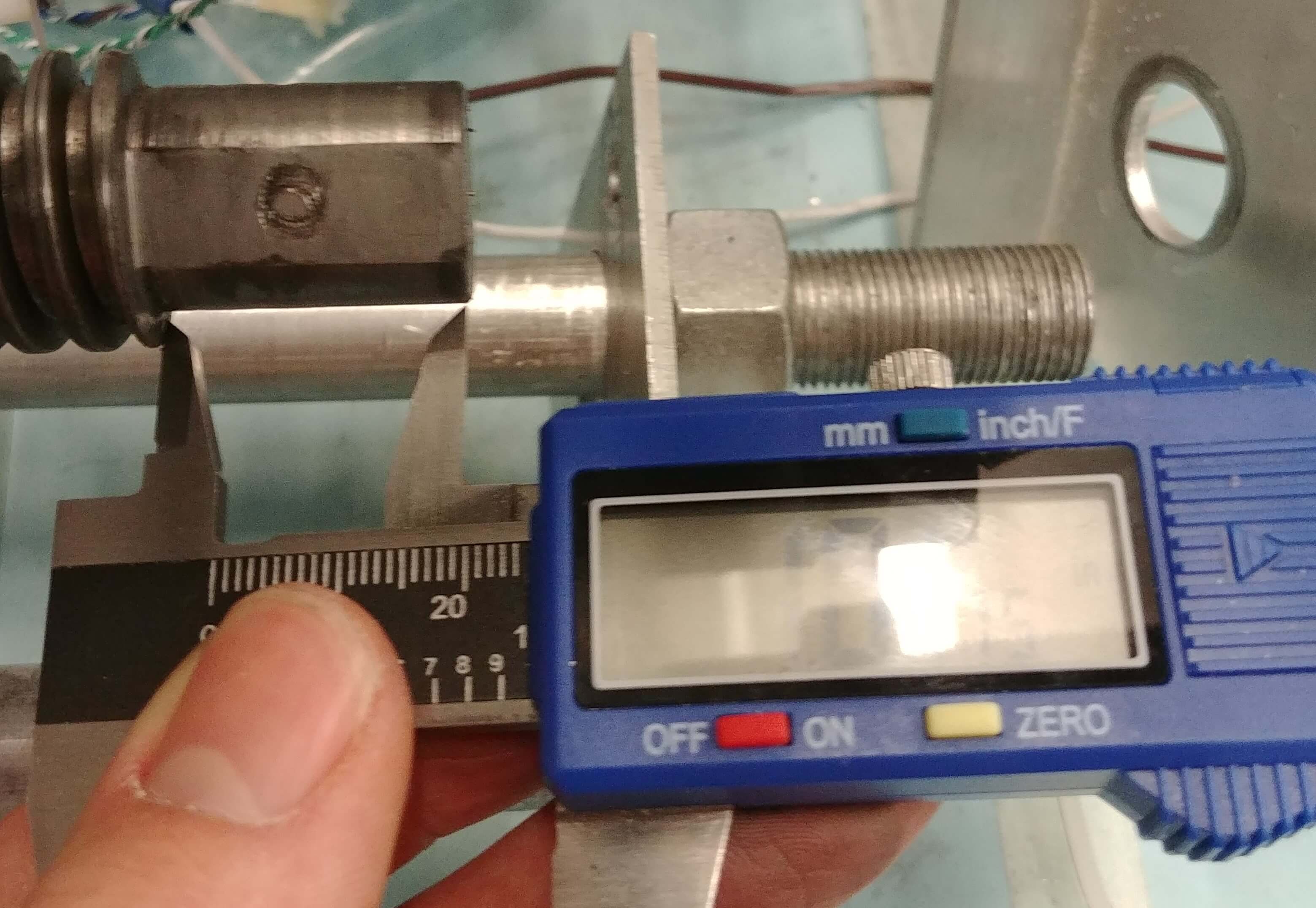
In that 1 inch (alright, the calipers actually read 1.0075 in this approximate measurement) I had to accommodate the thrust load from the weight of the elevator and everything on it, transmit torque to the lead screw, and make sure a sufficient amount of the shaft went through a bearing attached to the bottom plate. 1 inch is not a lot of space to accomplish all of this.
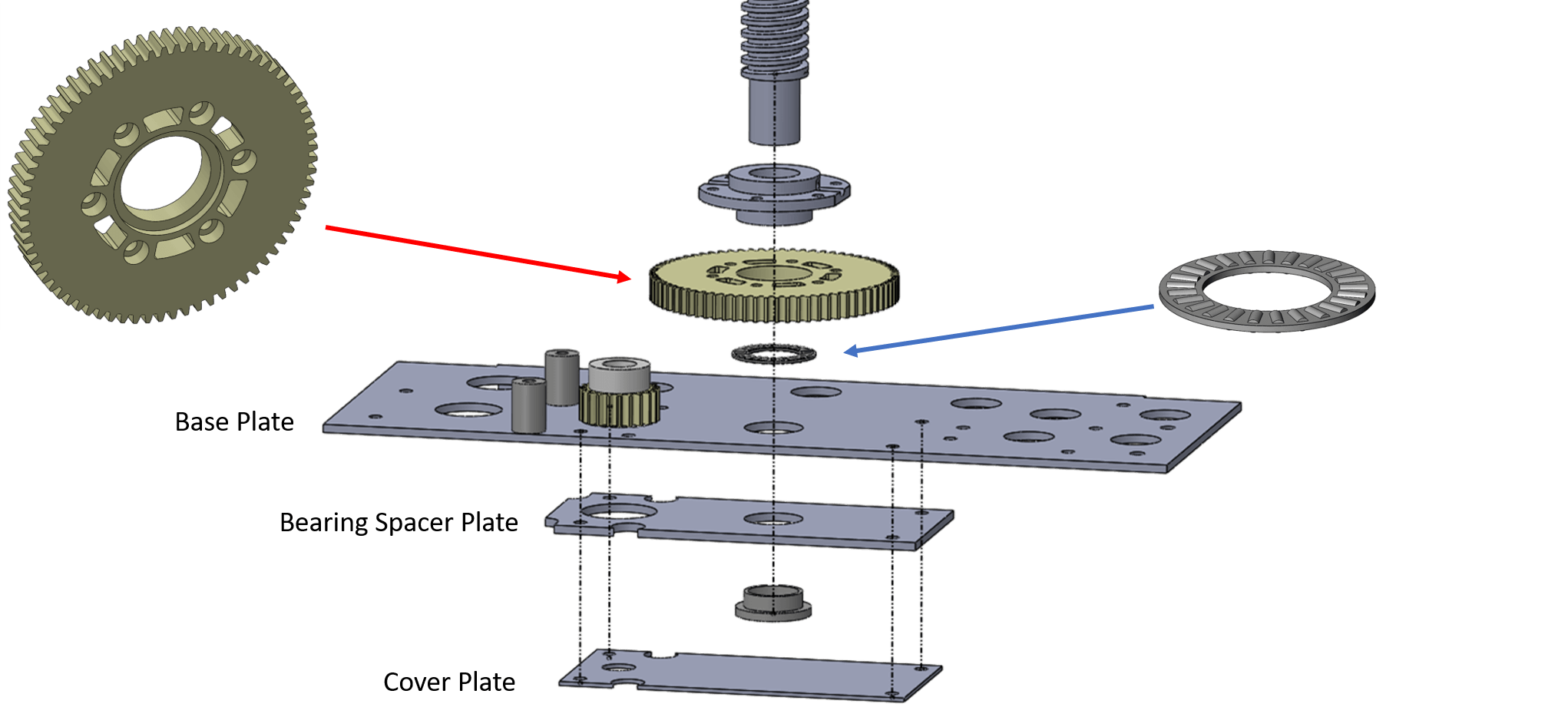
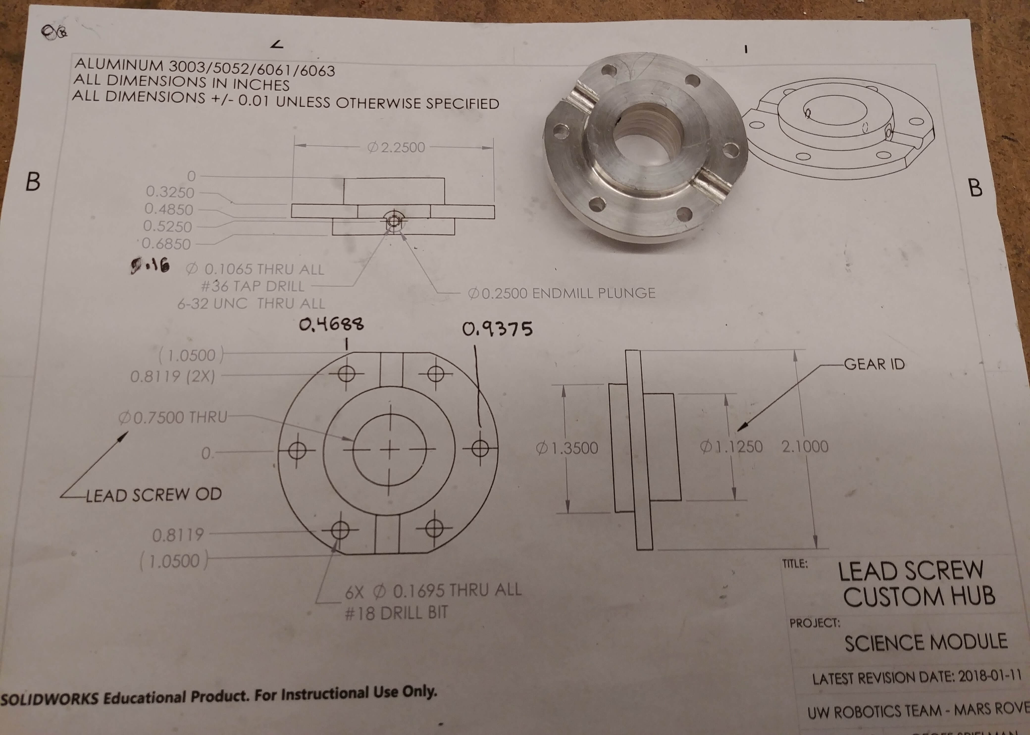
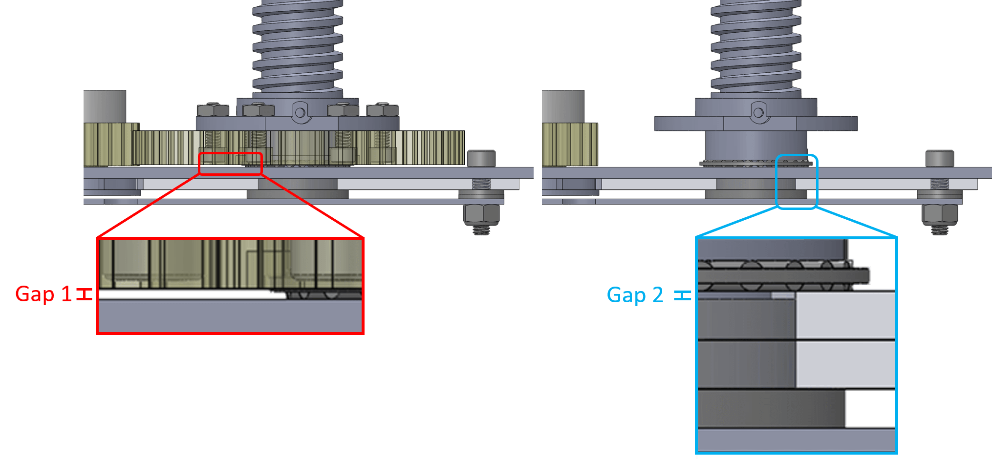
I started with a gear with the largest bore I could find and then designed a custom hub to fit inside it. The hub clamped onto the lead screw via two opposing set screws and SHCS recessed in counterbored holes in the gear fastened the gear to the hub. I used a needle roller bearing to take the thrust load and milled out a recess in the bottom of the gear to accommodate it. The hub went through the gear and transferred the thrust load directly to the needle roller bearing which meant I had to face off the hub perfectly on a lathe to ensure there was a tiny gap between the gear and the bottom support plate (gap 1) without wasting any of the precious shaft length. To accommodate the radial load I used an inverted flanged sleeve bearing and added an additional spacer plate between it’s flange and the base plate. I milled it the bearing off to just below the top surface of the base plate to prevent any interferences with the needle roller bearing (gap 2).
The last cover plate was added to retain the flanged sleeve bearing (our team avoids press fits for reusability/disassembly purposes) and to prevent
dust from getting in. Luckily the machining went really well and I was able to create exactly what is shown in the pictures above.
Conclusion
This was one of my most complicated design and machining projects and I’m really glad everything worked out. Below I’ve included several more pictures of the science module in various stages of development. I’ve also embedded our design team’s SAR (systems acceptance review) video starting when the module is first introduced so that you can see it in action. This video was submitted to a panel of judges back in February to determine if we would be accepted into the competition. From the 95 teams that applied, we were selected as one of the 36 teams from around the world that will be competing in Utah this June.