Autonomous Wall Climbing Robot
The Team
In my 3B semester I took a mechatronics design course and worked with 3 classmates (Will Clark, Tom Meredith, and Will Thibault) to build an autonomous wall climbing robot. I took care of the mechanical design and left the electrical and software aspects of the project in their capable hands.
The Task
The robot had to perform a ‘search and rescue mission’ which entailed scaling a 1 m tall ‘mountain range’, ‘picking up a stranded person’ on the far side by touching a target platform, and returning to the base station. There were several sheets of metal around the middle of the wall and a ramp on the right side to aid in our ascent. Here’s a sketch of the course:
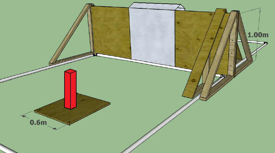
Additionally, the target platform on the far side of the wall could be placed anywhere on the course (randomly decided on demo day), and the robot had to complete the task autonomously (no remote control or human intervention permitted). Teams were scored based on the mass of their vehicle and the time it took to complete the mission; the goal was to minimize both.
The First Prototype
After a few weeks of concept sketches and discussions, we decided to take the magnetic wall climbing approach because we thought it would be more repeatable than aligning a robot with the very narrow ramp and staying on the ramp for the entire ascent. After a few more weeks of designing, ordering parts, wiring, and assembling we had our first prototype.
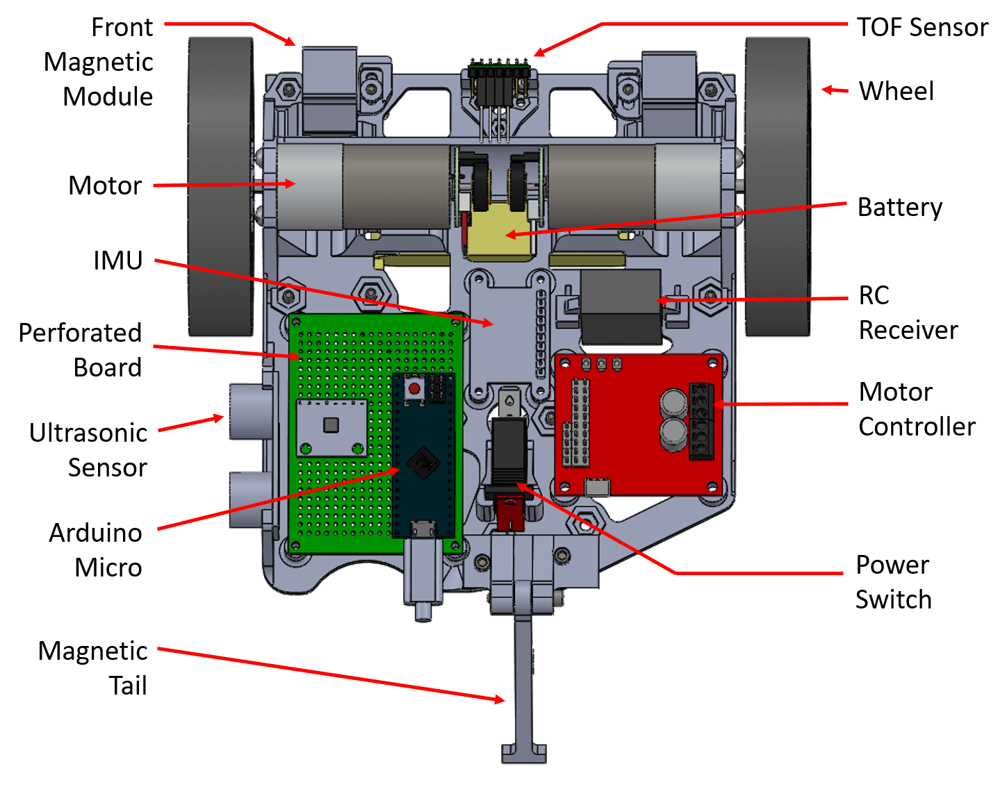
We decided to put the magnets in the treads to maximize the number of magnets in contact with the wall at a time. The motors were attached to the front left and back right wheels to keep the robot compact (the motor bodies were relatively long). We used brushed DC motors with integrated encoders and planetary gearheads to minimize mechanical and software complexity. A motor controller capable of closed loop speed control was purchased to ensure driving perfectly straight was achievable. All of the electronics were attached to a 3D printed ‘electronics chassis’ (white in the images below) which could be removed from the robot via 4 screws for ease of development and debugging. The main onboard processor was an ‘Arduino Micro’ microcontroller, purchased for its small size and ease of development. A time of flight sensor (TOF sensor) was mounted on the front of the robot to detect the target platform and base station when returning. Time of flight sensors essentially use echolocation: they emit infrared pulses of light and measure how long they take to return to estimate the distance between the sensor and whatever it’s pointed at.
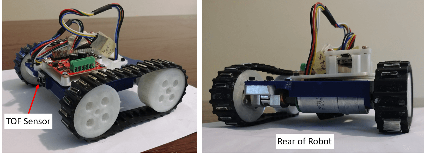
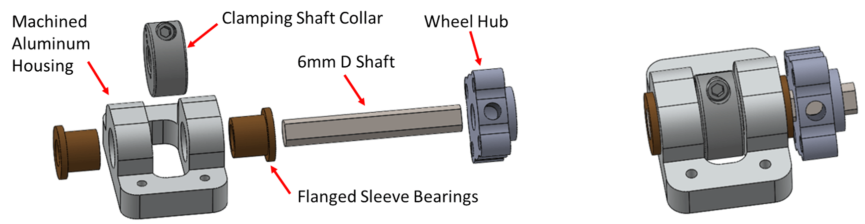
The driven wheels were attached to the robot with a compact bearing/shaft collar combination shown below. The wheels were 3D printed to match the pitch of the Lego tank treads used and to fit around the wheel hubs purchased.
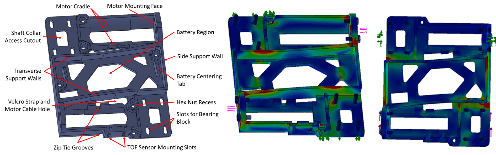
The chassis was 3D printed which allowed for a highly customized design. The images below show some of the features designed into the chassis and results from 2 of the FEA simulations performed. Drop tests, moment loads, and various force simulations were performed to capture the worst case loading on the robot in several circumstances while completing the mission. The simulation results were used to further reduce the weight of the chassis while strengthening key stress points. The next iteration of the chassis was approximately 30% lighter and felt significantly more rigid.
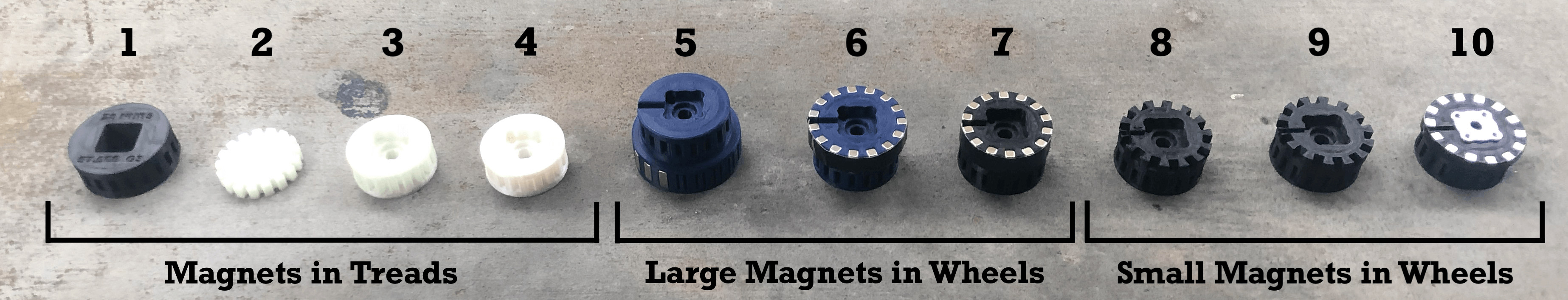
After some initial tests, most of the magnets tore off the treads and stuck to the steel wall. We tried several different glues and epoxies, but none could keep the magnets on the treads. Wrapping over the treads with tape and filling the magnet cavities with epoxy rendered the treads inoperably stiff. We decided to embed the magnets in the wheels of the robot instead.
Moving the Magnets into the Wheels
We purchased stronger, larger magnets and redesigned the wheels with spaces for the magnets to be pressed into. The first iteration of the new wheel design allowed the robot to climb up the metal wall with ease, however it was impossible to drive off the wall - the magnetic force was too strong. After several iterations to change the distance between the magnets and the wall and downsizing to lighter, less powerful magnets, the optimal level of magnetic force was achieved. In total, 10 wheel iterations were produced up to this point. Owning a 3D printer was very beneficial for rapid prototyping.
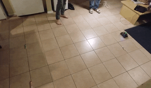
The two gifs below show the robot on flat ground and getting on and off a simulated wall (a testing rig I made).
Up until this point the course had not been constructed yet: we were designing our robots based the sketch shown previously and could not test on the real wall. Once the course was finally available, we found out that our robot couldn’t get over the first bend of the metal. The tread tension was adjustable, and we were hoping that the treads would deform enough to keep our front wheels in contact with the top of the wall at the first bend. Despite excessive slack in the treads, they did not flex enough and the robot tipped backwards as the front wheels lost contact with the wall.
We couldn’t use more powerful magnets on the front wheels otherwise we wouldn’t be able get off the wall at the bottom, so the decision was made to abandon tank treads.
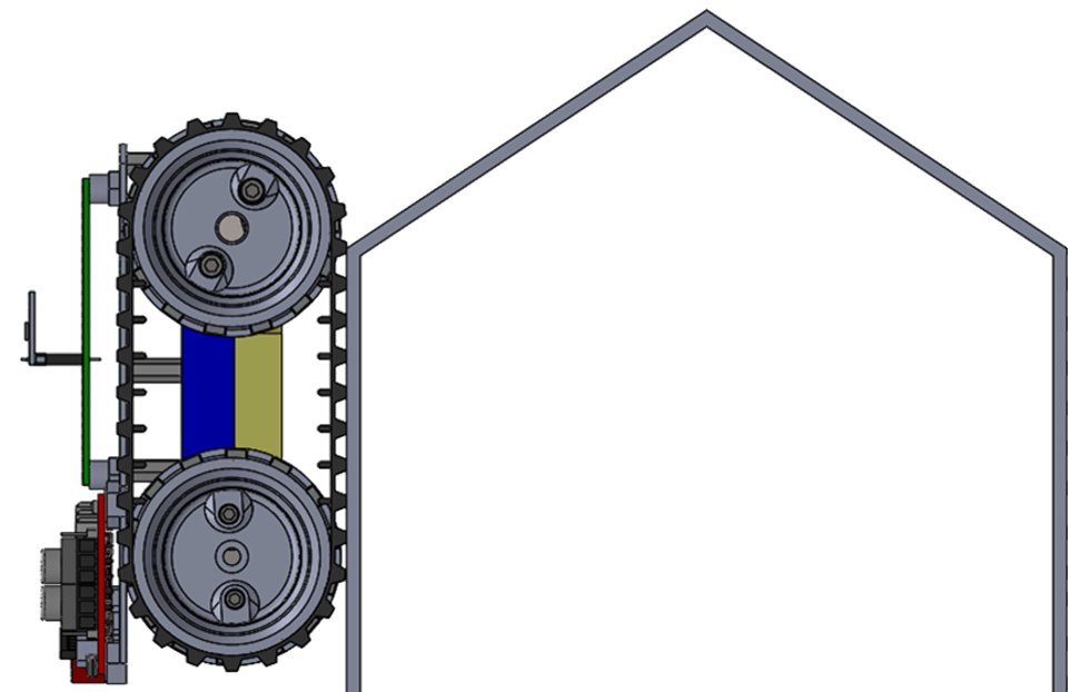
From Treads to Chains
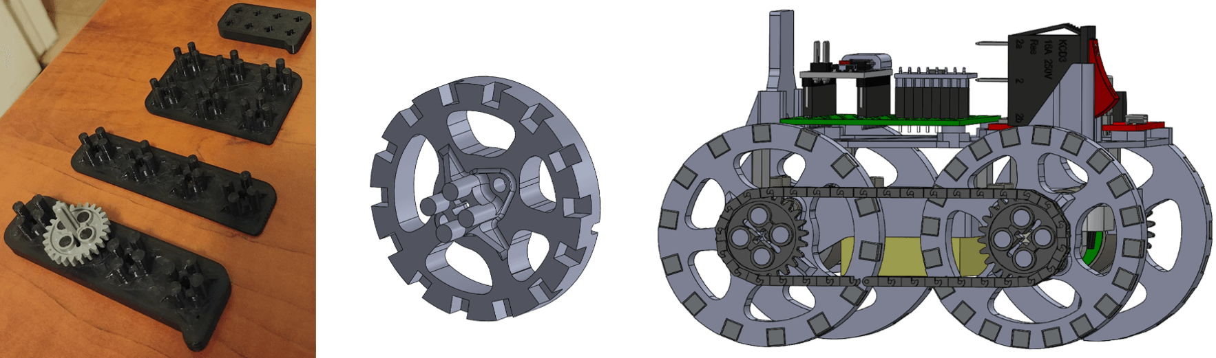
There were only two motors on the robot, and they were mounted directly to opposite wheels (front left and back right). To transmit power to the other two wheels, we tried sourcing tiny timing belts or chains but had no luck. Fortunately, a friend of mine lent me some Lego chains and sprockets. After a few test prints to get the fit just right (left image), I printed some new wheels and we tried out the chain design you see on the right.
Unfortunately, when transitioning from the ground to the wall, the tension in the chains was too high for the plastic Lego pieces and the chains broke apart. At this point we decided to abandon chains and the ‘motors on opposite wheels’ design.
Two Wheels and a Ball Caster
We decided to make our robot wider, use only two driving wheels, and add a ball caster to the back of the robot with magnets on either side. These magnets prevented the robot from flipping forward when descending the wall. With these modifications our robot could get over the first two bends in the wall…. most of the time. About every 4th test the robot would fall off the wall at the first bend. Eventually we determined this was because the wheels met the bend at different points in their rotation each test. If the bend met the wheels between two magnets (we called these regions ‘deadzones’) there would not be enough magnetic attraction to keep the robot on the wall. Reliability was one of our main design objectives since we only had 15 minutes on the course during demo day and were penalized for retries, so another design iteration was required.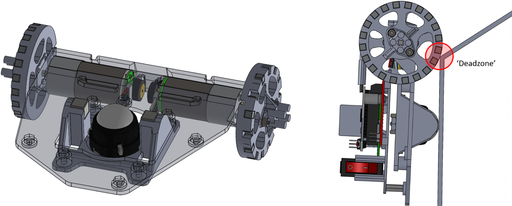
Adding the ‘Magnetic Modules’
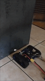
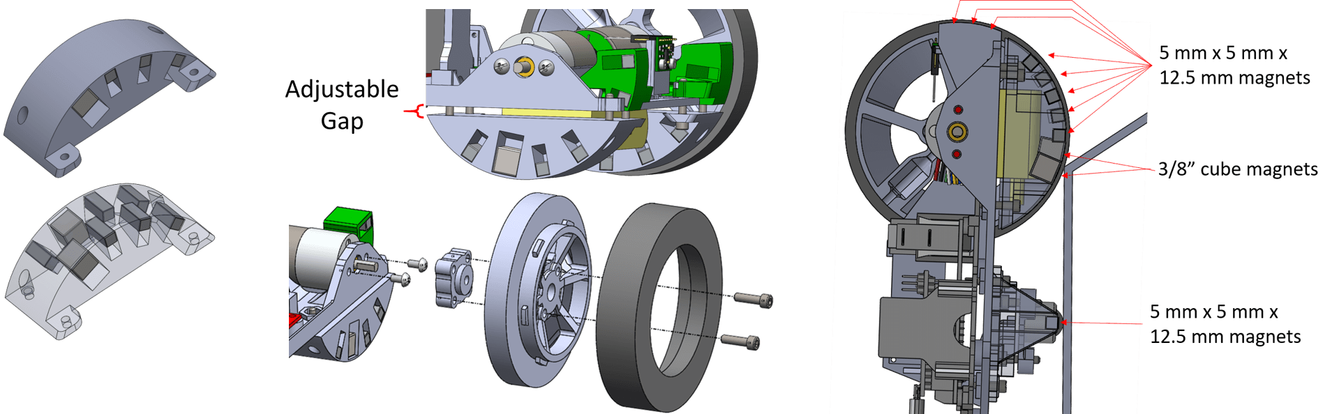
Instead of having the magnets embedded in the wheels, I designed some static semicircular ‘magnetic modules’ with the magnets embedded in them. I added some larger, more powerful magnets near the bottom which eliminated the ‘deadzone’. The gap between the magnetic modules and the robot chassis could be adjusted by varying the spacers used (washers and pieces of cardstock) to give us the optimal amount of magnetic force (enough to stay on the wall but still get off on the far side). I also added some smaller magnetic modules at the front of the robot (green) to provide the necessary force when transitioning from flat ground onto the wall.
As the scanning and steering software approached completion and the robot was turning and travelling faster, we noticed that despite the rubber tape wrapped around the 3D printed wheels they sometimes slipped due to poor friction. We went to Home Hardware hoping for a quick solution and bought two toilet bowl gaskets which were made of a soft, somewhat tacky rubber. We cut a ring out of them, I designed a rim, and suddenly we had wheels with unbelievably good grip. With the new magnetic modules and improved wheels, we could finally reach the top of the wall reliably.
Getting Down the Wall
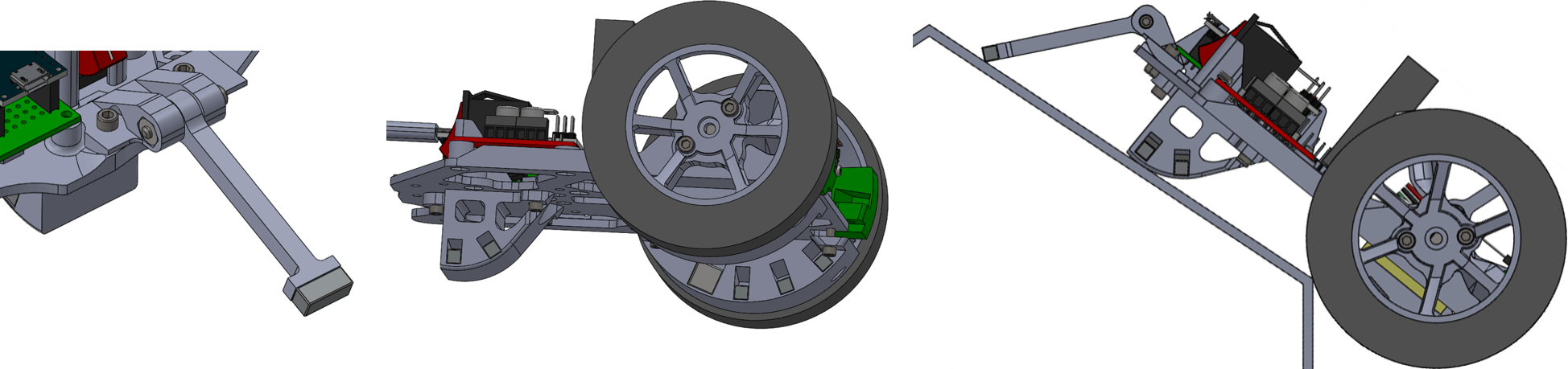
There were two problems preventing us from driving down the wall. First, the robot would flip forwards as soon as its front wheels got over the last bend since most of the robot’s mass was near the wheel centers (where the motors and magnetic modules were). To mitigate this, a magnetic tail was added to keep the rear of the robot against the wall while driving over the last bend.
Second, the metal wall was made from separate sheets of steel bolted together and there was a large gap between the downwardly sloped (second last sheet) and vertical (last sheet) segments. Our ball caster would sometimes get caught in this gap. The jolt of pulling the caster free caused the rear end of the robot to lose contact with the wall, sending the robot tumbling forward. To resolve this issue, the rear ball caster was replaced with a skid which was smooth along the front to glide over the gap in the wall. The skid was also 63% lighter than the ball caster module which helped increase our score.
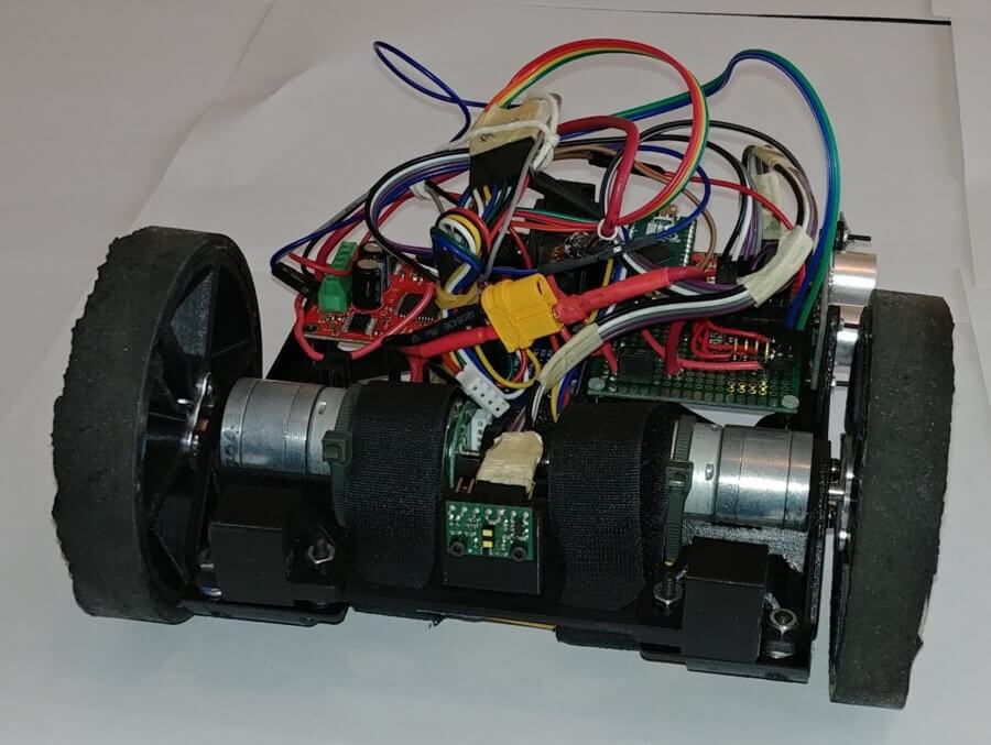
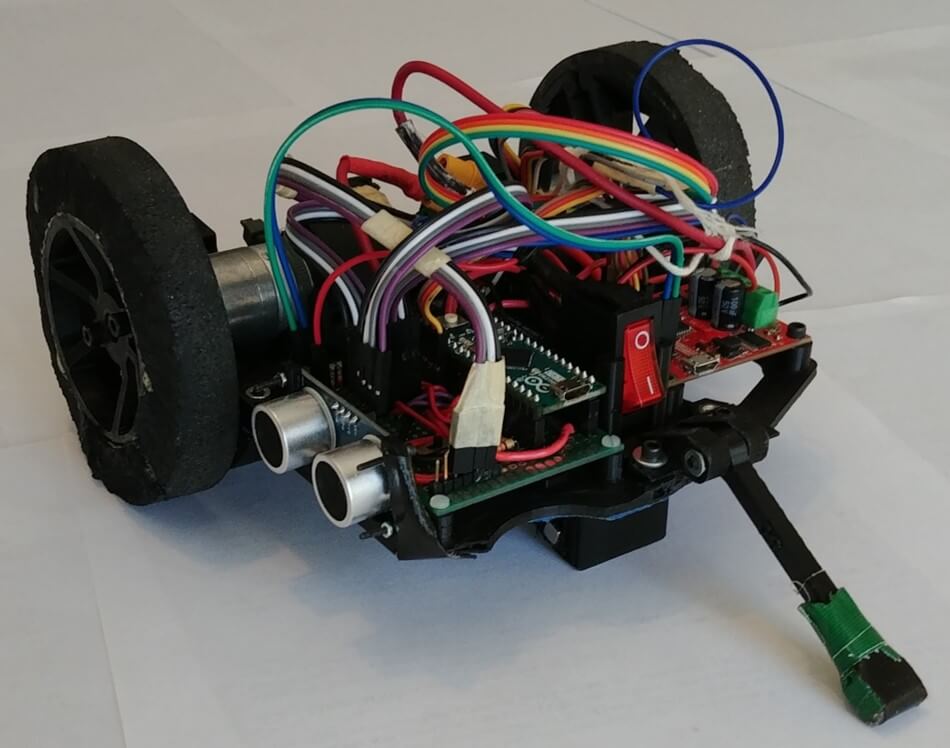
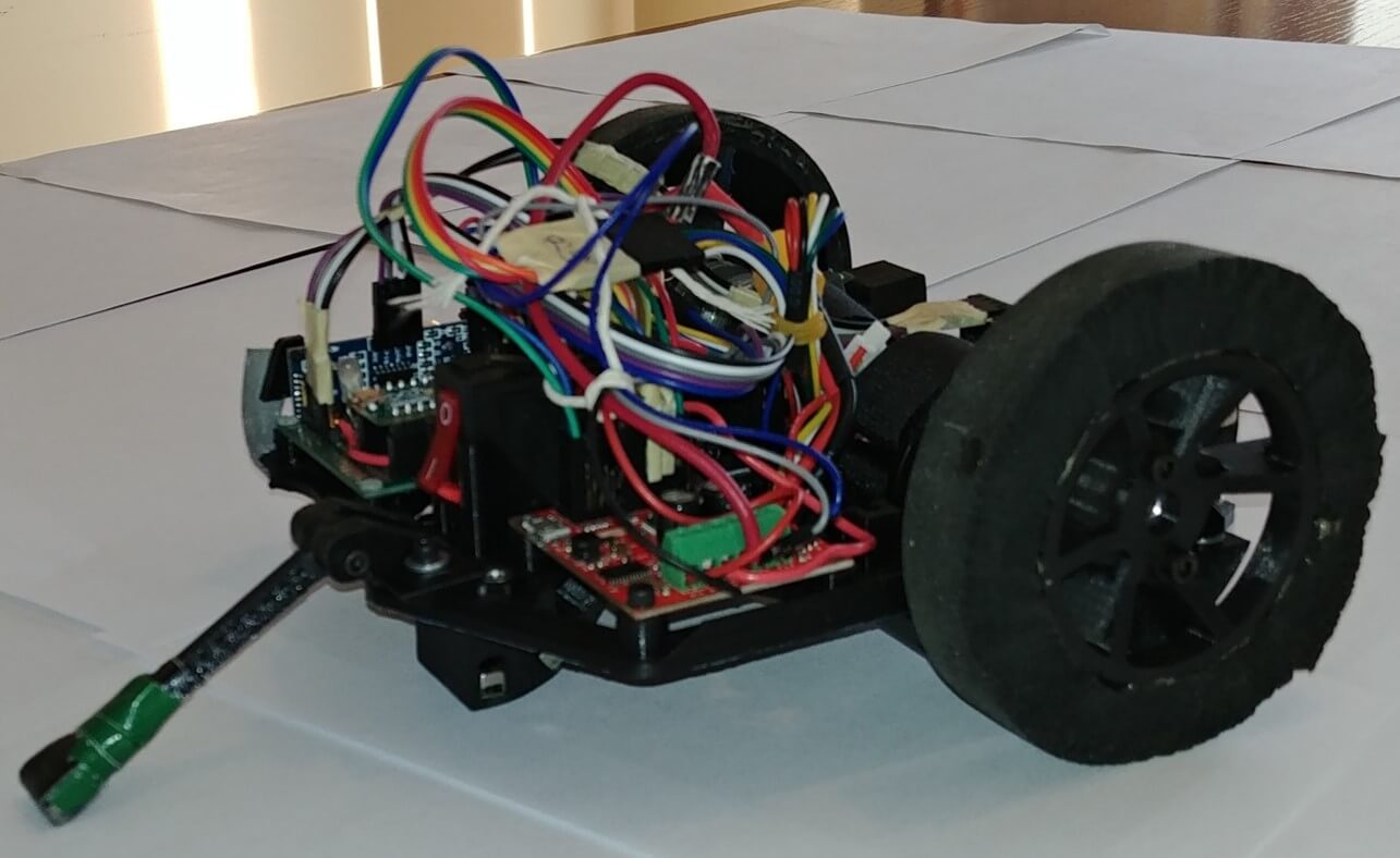
The Final Design
The previous sections focussed primarily on the mechanical evolution of the design, but there were simultaneous developments on the electrical and software aspects of the project as well. The time of flight (TOF) sensor’s datasheet claimed it had +/- 1 mm of accuracy with a range of 4 - 400 cm, however it only gave reliable readings at distances under 150 cm in a completely dark room. Since the robot needed to locate the target and base platforms in a well-lit classroom at distances far greater than 150 cm, an ultrasonic sensor was added to the robot for long range, low resolution scanning. Our new seeking algorithm was to approximately locate the target/base platforms using the ultrasonic sensor (since it has a very wide cone of detection), drive towards them, and then perform a second, more precise scan with the TOF sensor to pinpoint the exact location of the target or base platform.
The removeable RC receiver on the back of the robot allowed for manually controlled testing (via a remote control) which was helpful in the design phase but was removed towards the end of the project to reduce weight since the robot became fully autonomous. The IMU (inertial measurement unit) was used to detect the orientation and acceleration of the robot to determine the current state (driving on flat ground vs on the wall) and to keep the robot level while ascending the wall so that both wheels reached the top simultaneously.
Robot Performance (Demo Day)
On demo day, our team was the only team to complete the entire mission without any human assistance on the first try. Other groups gave their robots little prods, pushes, or carried it for part of the mission at the cost of a score penalty. As a result, we placed first in the competition ranking.
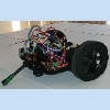
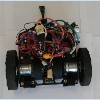
The final robot had a mass of 688 grams and completed the mission within 46 seconds. Below is a video from one of our test runs two days before demo day. The robot drives into the left wall of the course to align itself since the robot sometimes came off the wall at unpredictable angles or wouldn’t be pointed directly at the wall prior to its second ascent. I should mention that the robots were not required to drive onto the plywood target/base platforms, they merely had to touch them. Below the video I’ve included some pictures of the final design.